Somebody commented that cheap class D amplifiers are typically configured with maximum gain and low input impedance, thus impacting its sound quality. I wonder whether we can simply raise the input impedance. Sorry if what I write here is common knowledge or incorrect.
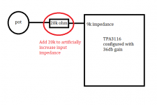
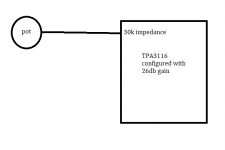
We'll use TPA3116s as example. Cheap TPA3116s are typically configured with 36db gain, thus an input impedance of 9k, while we might prefer a more reasonable gain of 20db or 26db. One typical DIY solution is to remove/replace R1 and R2 to bring the gain back to 20db or 26db.
Instead of modding the gain settings, can we simply add an additional resistor at input to raise the input impedance? Using the same example above, we add a 20k resistor at input to artificially raise the input impedance to 29k. This essentially drops the gain down to 26db. We can then add the volume pot on top of this, as if the input impedance is 29k.
This probably works best with amplifiers that don't come with volume pots or op amps.
Attachments

It will work but you may get more noise from the series R.
Is the 9k input a problem? If it isn't, you can make a 10dB attenuator that does not increase noise as much, like 10k series R into 3k parallel R.
Jan
I believe for some sources the 9k ohm might be too low and introduces static noises, so a higher input impedance is desirable is those cases.
Can you explain why the 20k ohm in series would introduce more noise?
Is 9K considered a low input impedance?
Attenuating the input of a high gain amplifier means any noise in the early stages of the amplifier is needlessly amplified.
Reducing the gain of the amplifier resolves this.
Of course, if the amplifier is quiet despite the high gain then no problem.
Attenuating the input of a high gain amplifier means any noise in the early stages of the amplifier is needlessly amplified.
Reducing the gain of the amplifier resolves this.
Of course, if the amplifier is quiet despite the high gain then no problem.
I suspect the reason the input resistor is low is to keep the feedback resistor low too.
I find with high value feedback resistors in op amps and chip amps you can start to get instability. This can sometimes be compensated for with a small capacitor in parallel with feedback resistor or a small capacitor across inverting/none inverting inputs.
I find with high value feedback resistors in op amps and chip amps you can start to get instability. This can sometimes be compensated for with a small capacitor in parallel with feedback resistor or a small capacitor across inverting/none inverting inputs.
The gain setting of TPA3116 etc works with additional internal series resistors before the input terminals. So adding an external series resistor of the same value should give the same resulting noise and THD as patching the gain setting divider.
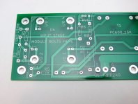
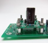
Thank you for your confirmation. I think working with so many TPA3116s have conditioned us to patch the gain setting dividers as the default solution. When we see a bare board like pictured, it might be easier just to use an external resistor in series instead.
Using an external resistor also allows us to choose whatever gain we want, so we are no longer confined to the typical 20db, 26db, 32db settings of TPA3116.
Attachments
Last edited:
Is 9K considered a low input impedance?
Attenuating the input of a high gain amplifier means any noise in the early stages of the amplifier is needlessly amplified.
Reducing the gain of the amplifier resolves this.
Of course, if the amplifier is quiet despite the high gain then no problem.
I am not sure myself. I have read a few posts that have attributed static noise to low input impedance (specifically with TPA3116 configured at 36db gain). I can't find a good source specifying what the range of desirable input impedance should be.
Last edited:
I believe the gain of the the TPA3116 is limited to one of 4 values. From the datasheet:
7.3.1 Gain Setting and Master and Slave
The gain of the TPA31xxD2 family is set by the voltage divider connected to the GAIN/SLV control pin. Master or Slave mode is also controlled by the same pin. An internal ADC is used to detect the 8 input states. The first four stages sets the GAIN in Master mode in gains of 20, 26, 32, 36 dB respectively, while the next four stages sets the GAIN in Slave mode in gains of 20, 26, 32, 36 dB respectively. The gain setting is latched during power-up and cannot be changed while device is powered. Table 1 lists the recommended resistor values and the state and gain.
I believe the gain of the the TPA3116 is limited to one of 4 values. From the datasheet:
7.3.1 Gain Setting and Master and Slave
The gain of the TPA31xxD2 family is set by the voltage divider connected to the GAIN/SLV control pin. Master or Slave mode is also controlled by the same pin. An internal ADC is used to detect the 8 input states. The first four stages sets the GAIN in Master mode in gains of 20, 26, 32, 36 dB respectively, while the next four stages sets the GAIN in Slave mode in gains of 20, 26, 32, 36 dB respectively. The gain setting is latched during power-up and cannot be changed while device is powered. Table 1 lists the recommended resistor values and the state and gain.
TI is obviously limited by their imagination. We are here to outdo them
")
The gain is limited to those 4 values because TPA3116 only lets you choose from 4 input impedance (9k, 15k, 30k, 60k). The gain is inversely correlated to the input impedance, so if we can fine tune the effective impedance, we can change the gain to an arbitrary value.
We can start with a TPA3116 that's configured to have 26db gain and 30k input impedance. By connecting an 8k resistor in series to the input pin, we can raise the effective input impedance to 38k (30k + 8k = 38k), and drop the gain to 24db in the process.
You can refer to post #2 Dealing with low input impedance of cheap amps above to see what I mean.
We're conducting a grand experiment over in the M2x power amp thread. M2x is a fairly conventional class A amp with a conventional linear power supply, unregulated. Its input circuit is a unity gain buffer which presents a nice high input impedance (>100K) to the external world, and which also provides plenty of output current to drive a low impedance (600 ohms) at the output ... just what is wanted here.
BUT
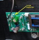
M2x's input circuit is removable and field replaceable. It's a simple "module" (PCB daughterboard) with four I/O pins: PosSupply, NegSupply, Input, Output. See Figures 1-3 below.
So far the M2x community has built and listened critically to at least eight different unity gain buffer circuits on these input cards. Schematics in pdf format attached below. Perhaps surprisingly, different listeners have different favorites -- they are sure they can hear differences among unity gain buffers, and some are preferable while others are not.
Quite a few M2x builders have strong opinions about which unity gain buffer sounds Best, and perhaps not surprisingly, there isn't universal agreement. Each buffer has its (vocal) supporters and each has its (moderately polite) detractors.
Perhaps one of the M2x input buffers would work nicely in this application too. You can peruse the M2x thread to see what builders & listeners are saying about each. Or if you feel that all unity gain buffers doubtless sound the same, you can choose one with the lowest BOM cost / the weirdest schematic / the greatest percentage of SMD parts / etc. No matter which one you choose, it will be a buffer with plenty of adamant supporters who love its sonic signature. If you care.
_
BUT
M2x's input circuit is removable and field replaceable. It's a simple "module" (PCB daughterboard) with four I/O pins: PosSupply, NegSupply, Input, Output. See Figures 1-3 below.
So far the M2x community has built and listened critically to at least eight different unity gain buffer circuits on these input cards. Schematics in pdf format attached below. Perhaps surprisingly, different listeners have different favorites -- they are sure they can hear differences among unity gain buffers, and some are preferable while others are not.
Quite a few M2x builders have strong opinions about which unity gain buffer sounds Best, and perhaps not surprisingly, there isn't universal agreement. Each buffer has its (vocal) supporters and each has its (moderately polite) detractors.
Perhaps one of the M2x input buffers would work nicely in this application too. You can peruse the M2x thread to see what builders & listeners are saying about each. Or if you feel that all unity gain buffers doubtless sound the same, you can choose one with the lowest BOM cost / the weirdest schematic / the greatest percentage of SMD parts / etc. No matter which one you choose, it will be a buffer with plenty of adamant supporters who love its sonic signature. If you care.
_
Attachments
Last edited:
I did more digging, and now I am not sure if adding an external resistor to the input pin will solve the typical noise issues experienced with high gain settings. I have a few TPA3116 boards that are configured with 36db gain and experience noise when turned high. I can experiment with them to see if I can discover more.
A quality source/preamp of today drives 10 kOhm with ease. I think this is a non issue in most setups (except for tube stuff but there any normal load is too much). If less than 1 mA drive is to worry about I think worrying about that source is more fitting
So in general 10 kOhm is not an issue, well if it makes one sleep better then put 2.2 kOhm in series with TPA3116/8 with worst case value of 9 kOhm is already adequate. In the various TPA3116/8 I have tried I never ran into issues with the 9 kOhm and always use the 20 db setting as the amplifiers then are most silent and adapted to normal signal levels of sources. A buffer is not needed.
A clean power supply is what is needed. When using an SMPS then the PO89ZB is a solution or do it right at once and build a regulated PSU.
Last edited:
TI is obviously limited by their imagination. We are here to outdo them
The gain is limited to those 4 values because TPA3116 only lets you choose from 4 input impedance (9k, 15k, 30k, 60k). The gain is inversely correlated to the input impedance, so if we can fine tune the effective impedance, we can change the gain to an arbitrary value.
We can start with a TPA3116 that's configured to have 26db gain and 30k input impedance. By connecting an 8k resistor in series to the input pin, we can raise the effective input impedance to 38k (30k + 8k = 38k), and drop the gain to 24db in the process.
You can refer to post #2 Dealing with low input impedance of cheap amps above to see what I mean.
Hi!
If this resistance is inductive ... it will spoil your signal.
Hi!
If this resistance is inductive ... it will spoil your signal.
Hi, is a regular resistor inductive at all? Wouldn't a volume pot have similar issues?
A quality source/preamp of today drives 10 kOhm with ease. I think this is a non issue in most setups (except for tube stuff but there any normal load is too much). If less than 1 mA drive is to worry about I think worrying about that source is more fitting
So in general 10 kOhm is not an issue, well if it makes one sleep better then put 2.2 kOhm in series with TPA3116/8 with worst case value of 9 kOhm is already adequate. In the various TPA3116/8 I have tried I never ran into issues with the 9 kOhm and always use the 20 db setting as the amplifiers then are most silent and adapted to normal signal levels of sources. A buffer is not needed.
A clean power supply is what is needed. When using an SMPS then the PO89ZB is a solution or do it right at once and build a regulated PSU.
Initially I thought that 9k input impedance is typically paired with low value volume pots (1k or 5k), which may lower the input impedance to even lower levels, causing problems.
But I realized that many of these boards actually use 45k or 50k volume pots, so I was wrong.
I think you are right, in my reasoning I thought of sources with volume control built in and then often the output is active. When passive volume control is between source and amplifier then normally the potentiometer is the same or lower in value as the input impedance of the amplifier. In that case the load would be way lower than 10 kOhm when such a potentiometer is used. Then I would calculate what it is and check if the source/buffer/preamp can drive it. Many will not have a problem with loads till even 1 kOhm but some will have too small output caps.
Using a 50 kOhm volume potentiometer for 9 kOhm setting of the TPA3116/8 is odd.
Using a 50 kOhm volume potentiometer for 9 kOhm setting of the TPA3116/8 is odd.
Last edited:
I think you are right, in my reasoning I thought of sources with volume control built in and then often the output is active. When passive volume control is between source and amplifier then normally the potentiometer is the same or lower in value as the input impedance of the amplifier. In that case the load would be way lower than 10 kOhm when such a potentiometer is used. Then I would calculate what it is and check if the source/buffer/preamp can drive it. Many will not have a problem with loads till even 1 kOhm but some will have too small output caps.
Using a 50 kOhm volume potentiometer for 9 kOhm setting of the TPA3116/8 is odd.
Thank you for understanding my point. I was worried it would have been too incoherent.
I did some analysis, and found that the effective impedance is always lower than the volume pot resistance. So if a 1k pot is used, the effective impedance is always 1k or lower. As you said some sources may drive it and some may not.
- Home
- Amplifiers
- Class D
- Dealing with low input impedance of cheap amps