Since 2014 I am developping my TPA-3118 amps from scratch including pcb-layout. Although I did the same with their bigger brothers TPA3255 as well, I like these chips for their simplicity and low standby current making them the ideal choice for battery powered amps. Over the years I added some useful features that are not covered by TI's app notes. Besides this I will add some basic remarks that may or may not be interesting or enlighting for you.
LC Output Filter, Snubbers and Post-Filter-Feedback
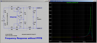
The LC-output filter exhibits a second order lowpass filter that reconstructs the pulsed PWM signal. Sadly this is only half of the truth. The other half: The class-D bridge output is loaded by a LC-series resonant tank. At its resonant frequency the series impedance drops close to zero, load current increases upto the limits and output voltage rises far beyond supply voltage. To avoid this destructive scenario you can either dampen the resonant tank or prevent excitation by strictly band-limited audio input. The mainstream attempt is dampening the LC-circuit with the speaker load according to the formula
Z(series tank) = sqrt(L/C) = R(speaker),
so with L=10uH and C=1u0
R(speaker) = sqrt(10) = 3,16 Ohms
Should be close to perfect for a 4 Ohm speaker. Well, I do not think so. For some reason nobody points out that dampening requires a strictly real (ohmic) impedance, measured at resonant frequency. With resonant frequencies in the ballpark of 30~50kHz this certainly works fine in the lab with non-inductive dummy loads. But in real world? Did you ever find speakers with 8 Ohm ohmic impedance at 50kHz? Let me say it frankly: No way, forget this! Voice coils of real speakers always incorporate some inductance that shows up in an increasing impedance toward higher frequencies. From this point of view it would be more realistic to measure frequency response without load. I would be very interested in any gain vs frequency plot of unloaded fixed pwm-clock class-D-amp, so if you find one, please let me know.
On the other hand todays audio sources are in 99.99% of the cases band limited to 20kHz making this danger look a bit unrealistic. Nonetheless you often find warnings that class-D amps should not be operated without load - here is the reason for that statement. Moreover this I find it annoying to match the output filter to various speaker impedance and so I searched for a solution. Snubbers came into my mind. And were dropped soon, because a working snubber must either be capable to dissipate full power of the amp - which is obviously unrealistic. Otherwise it is taylored to survive - without having any effect. Remember all these burned snubber resistors on audio amps? No and no!
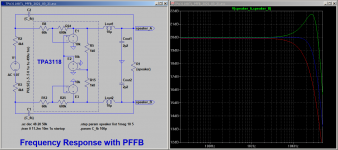
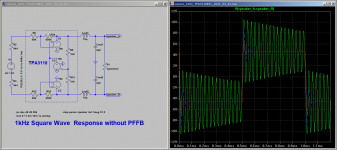
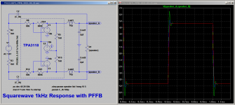
So let us go for post-filter feedback. This promises not only to tame the resonant peak but flattens the overall frequency response resulting in much better square wave response, nearly independent of speaker impedance. No snubber, no need to fine tune output filter depending on your speaker, no problem operating the amp without load...
After this lengthy introduction the implementation is surprisingly simple: A differentiating RC-feedback network between filtered output and input - that's all! It should be mentioned that this variant of PFFB network is quite different from the common type you will find in many debates around here. Opposed to "normal" feedback networks, the amount of feedback increases with frequency. So it is most effective in taming the high frequeny peak at resonance but with very little effect in the audio band: Do not expect signifant reduction of THD - this is not in my focus here. My priority was stability, not mind-blowing THD figures. To give an idea I simulated the TPA3118 without and with PFFB:
LC Output Filter, Snubbers and Post-Filter-Feedback
The LC-output filter exhibits a second order lowpass filter that reconstructs the pulsed PWM signal. Sadly this is only half of the truth. The other half: The class-D bridge output is loaded by a LC-series resonant tank. At its resonant frequency the series impedance drops close to zero, load current increases upto the limits and output voltage rises far beyond supply voltage. To avoid this destructive scenario you can either dampen the resonant tank or prevent excitation by strictly band-limited audio input. The mainstream attempt is dampening the LC-circuit with the speaker load according to the formula
Z(series tank) = sqrt(L/C) = R(speaker),
so with L=10uH and C=1u0
R(speaker) = sqrt(10) = 3,16 Ohms
Should be close to perfect for a 4 Ohm speaker. Well, I do not think so. For some reason nobody points out that dampening requires a strictly real (ohmic) impedance, measured at resonant frequency. With resonant frequencies in the ballpark of 30~50kHz this certainly works fine in the lab with non-inductive dummy loads. But in real world? Did you ever find speakers with 8 Ohm ohmic impedance at 50kHz? Let me say it frankly: No way, forget this! Voice coils of real speakers always incorporate some inductance that shows up in an increasing impedance toward higher frequencies. From this point of view it would be more realistic to measure frequency response without load. I would be very interested in any gain vs frequency plot of unloaded fixed pwm-clock class-D-amp, so if you find one, please let me know.
On the other hand todays audio sources are in 99.99% of the cases band limited to 20kHz making this danger look a bit unrealistic. Nonetheless you often find warnings that class-D amps should not be operated without load - here is the reason for that statement. Moreover this I find it annoying to match the output filter to various speaker impedance and so I searched for a solution. Snubbers came into my mind. And were dropped soon, because a working snubber must either be capable to dissipate full power of the amp - which is obviously unrealistic. Otherwise it is taylored to survive - without having any effect. Remember all these burned snubber resistors on audio amps? No and no!
So let us go for post-filter feedback. This promises not only to tame the resonant peak but flattens the overall frequency response resulting in much better square wave response, nearly independent of speaker impedance. No snubber, no need to fine tune output filter depending on your speaker, no problem operating the amp without load...
After this lengthy introduction the implementation is surprisingly simple: A differentiating RC-feedback network between filtered output and input - that's all! It should be mentioned that this variant of PFFB network is quite different from the common type you will find in many debates around here. Opposed to "normal" feedback networks, the amount of feedback increases with frequency. So it is most effective in taming the high frequeny peak at resonance but with very little effect in the audio band: Do not expect signifant reduction of THD - this is not in my focus here. My priority was stability, not mind-blowing THD figures. To give an idea I simulated the TPA3118 without and with PFFB:
Attachments
Last edited:
Awesome work. I've been struggling to understand the LC output filter behavior on these boards-- I got a bunch of cheapos to toy with. I'm nowhere near your pay-grade in comprehension but you're helping me grok what's going on a little better. I'd like to make things that play nice with any speaker.
Thank you.
Edit: as stated, I'm below pay-grade, but I'm trying to understand how you calculate the values for C1 and C2. Should I dig through here? Your implementation seems much simpler or maybe I'm misreading
Thank you.
Edit: as stated, I'm below pay-grade, but I'm trying to understand how you calculate the values for C1 and C2. Should I dig through here? Your implementation seems much simpler or maybe I'm misreading
Last edited:
This TI appnote is well known and it is a good idea to read it. Anyway I took it with a grain of salt and my PFFB approach is quite different with its goal and implementation. The best you can do take my LTspice simu and play with it.
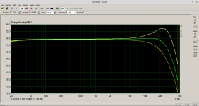
It should be mentioned that the input series resistor being part of the PFFB-network must be driven by a low impedance op-amp output. This is simulated by a driving voltage source. Driving impedance above 1kOhm will change the behaviour, and with input open the amp wildly oscillates:
You definitely will need an input buffer with this type of PFFB.
And, yes, my implementation is much simpler")
It should be mentioned that the input series resistor being part of the PFFB-network must be driven by a low impedance op-amp output. This is simulated by a driving voltage source. Driving impedance above 1kOhm will change the behaviour, and with input open the amp wildly oscillates:
You definitely will need an input buffer with this type of PFFB.
And, yes, my implementation is much simpler
Last edited:
It would seem that using an OPA1637 as SE to Bal buffer would be perfect to make the TPA3116/8 work well with PFFB. Add 6dB of gain while we are at it to get 28dB overall gain. Better than tying one channel’s input cap to ground for BTL. This would indeed be an easy and fun little board to make. I would add a SSR with delay and instant off to prevent the arch nemesis of the TPA311x - turn on/off thump.
Anyone want to take a first crack at the layout?
Anyone want to take a first crack at the layout?
A very interesting subject that is often overlooked indeed!
Great post!
The cheap way to get by a little (but really just a little), is to make a zobel network (I guess what you call a snubber?)
Staying with inductors, is also that a lot of boards (even professional ones) use the wrong type of inductor.
Also with this again TI has quite a lot of documentation to support this, but basically just really stay away from any inductor that has a soft saturation curve.
Usually these are like soft iron cores, or molded inductors (basically anything that isn't ferrite). Although these inductors work great for buck/boost converters, they will introduce a substantial amount of distortion.
What you want is that the inductance stays constant at all time.
Another point that is often overlooked (an really can be found as a problem with cheaper PCB designs), is that you need to design the inductor with the PEAK current in mind.
I have also seen this gone wrong with quite professional designs actually.
So most people have a tendency to just only think about the RMS or average power (current) that is being used. The issue with this, is that the higher part of the current sine wave is basically distorting (see it like a compressor, which it basically is)
So when designing a board a determining the inductor to be used, you need to think about the max peak current as a limit and then look at the saturation graphs (= inductance vs current). Good manufactures even have a inductance vs current vs temperature graph, since the inductor will saturate quicker with higher temperatures.
Of course there will be a trade-off with costs and board real-estate, so I often take 5-10% drop in inductance as a starting point as the maximum peak current.
And interesting idea on the PFFB concept, is to make some kind of composite amp.
This has been done with inverting linear amplifiers, so I don't see why it can't be done with a switching amplifier?
That way you can not only get a nice perfect frequency response, but also reduce distortion significantly.
Oh and btw, yeah the TPA325x family are better, but like you, the PCB design is a pain in the behind.
btw 2: You don't have to use STEPS for this, but can just sweep in ARTA (incl THD results)
Last edited:
All this above are valuable points for me, nothing to disagree. I measured inductors distortion sometimes with a non-switichng class AB-amp and yes - ferrite is the only way to go for lowest THD. Al cheapo toroids and carbonyl are the worst.
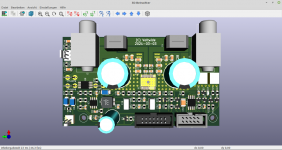
Concerning pcb-layout - last time I took my existing TPA3251 layout and "downgraded" it to TPA3118 with some other amendments I will propose later on. As I never go beyond 2-layer layouts, it took me 2 tht-wire strips for a reasonable routing for the TPA325x. These were not required with TPA3118.
Concerning pcb-layout - last time I took my existing TPA3251 layout and "downgraded" it to TPA3118 with some other amendments I will propose later on. As I never go beyond 2-layer layouts, it took me 2 tht-wire strips for a reasonable routing for the TPA325x. These were not required with TPA3118.
All this above are valuable points for me, nothing to disagree. I measured inductors distortion sometimes with a non-switichng class AB-amp and yes - ferrite is the only way to go for lowest THD. Al cheapo toroids and carbonyl are the worst.
Concerning pcb-layout - last time I took my existing TPA3251 layout and "downgraded" it to TPA3118 with some other amendments I will propose later on. As I never go beyond 2-layer layouts, it took me 2 tht-wire strips for a reasonable routing for the TPA325x. These were not required with TPA3118.
Yeah, it was nothing more than just some additional information on the subject
Why do you stick with two layer boards?
4 layer is basically the same price these days at it will just give only so many advantages! Especially taking EMI etc into consideration.
I was just playing around with LTSpice, but it looks like up to around 5k6 is still very doable and stable?
That doesn't seem to be too heavy on any input or buffer?
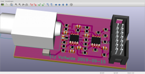
I do not know exactly what the "composite amp" is. My power PCBs strictly exclude any buffers, pr-amps or opamps. Both inputs are directed to an IDC connector that will be connected through ribbon cable with a small AFE (audio front end). This gives me the flexibility to quick change between quite different interface concepts. Something like that
Attachments
Last edited:
Yeah, it was nothing more than just some additional information on the subject
Why do you stick with two layer boards?
4 layer is basically the same price these days at it will just give only so many advantages! Especially taking EMI etc into consideration.
I was just playing around with LTSpice, but it looks like up to around 5k6 is still very doable and stable?
That doesn't seem to be too heavy on any input or buffer?
At the time I do not see the 4 layer being so promising - and to be honest - I am a lazy guy as well.
I do net get what you are talking about with 5k6 - input series resistor?
At the time I do not see the 4 layer being so promising - and to be honest - I am a lazy guy as well.
I do net get what you are talking about with 5k6 - input series resistor?
Well, if you want to go for lazy, 4 layer is the way to go!
It makes everything so much easier!
Yes, 5k6 input resistor
A composite (or nested) amplifier, is basically taking another (power) amplifier and put it inside the loop of another one.
Very popular atm is for example the LM3886 with an opamp of your taste.
It can be done with inverting and non-inverting amplifiers.
Composite Amplifiers: High Output Drive Capability with Precision | Analog Devices
I see. Yes, I thought of that some time ago. But I dropped this idea - because there are big problems in feeding the class-D-output signal with its big pwm-clock content to an analogue input of an op-amp. I admire the TPA-internal comparators that can deal with full swing pwm output
So I concluded not to use an outer loop - but using the internal op-amps more extensively. It can be shown that by programming the max gain and using an external post feed-back network you can reduce distortion by one order reaching the ballpark of TPA3251. And this is an option the TPA325x do not offer. There exists some simulation and real measurements I did in the past so I have to look at....
So I concluded not to use an outer loop - but using the internal op-amps more extensively. It can be shown that by programming the max gain and using an external post feed-back network you can reduce distortion by one order reaching the ballpark of TPA3251. And this is an option the TPA325x do not offer. There exists some simulation and real measurements I did in the past so I have to look at....
Last edited:
I see. Yes, I thought of that some time ago. But I dropped this idea - because there are big problems in feeding the class-D-output signal with its big pwm-clock content to an analogue input of an op-amp. I admire the TPA-internal comparators that can deal with full swing pwm output
So I concluded not to use an outer loop - but using the internal op-amps more extensively. It can be shown that by programming the max gain and using an external post feed-back network you can reduce distortion by one order reaching the ballpark of TPA3251. And this is an option the TPA325x do not offer. There exists some simulation and real measurements I did in the past so I have to look at....
I will be very curious about your findings with this and reducing the distortion!
I actually never gave it much thought to be honest lol
About the composite idea.
As far as I know it's just about only "correcting" the audio freq band.
So basically when you prevent the switching freq (400-500kHz) from going into the diff amp (first stage) that should be fine.
Since the switch freq signal is already quite low after the LC filter, I think something like a parallel capacitor on the feedback resistor will maybe already do quite a lot. Or some other kind of pre-filtering before going back to the feedback loop (although that could cause oscillation again......)
But I also dropped the idea, more just lack of time lol
- Home
- Amplifiers
- Class D
- Class-D with TPA3118 - An Update after all these Years