LEDs are run on current, not voltage. That should be somewhat clear after 8 months. Current is measured in series but you can of course also measure the voltage over the current limiting series resistor and calculate. This is the formula anyone working with LEDs should know by head:
Iled = Ub - Uf led/Rseries so ... Rseries = Ub - Uf led/I led. A normal modern LED glows already with 2.5 mA. So with 5V power supply and a green LED it will be 5V - 1.6V/0.0025A = 1360 Ohm. This would be a 1.5 kOhm in real life.
The LED would have functioned just as fine on the designated pins of header P102 with added function of overheating indication. With a white or blue (terrible!) LED Uf is around 3 to 3.5V. So with the 5V of the 50ASX2SE board this would be 5V - 3.5V/0.0025 = 600 Ohm. In real life we pick 560 Ohm or 680 Ohm. If unsure then recalculate with real life values. The habit is to pick the next higher value for slightly less current.
For a dim glowing (terrible) blue or white LED one would have needed a LED and a resistor of 680 Ohm.
Last edited:

LEDs are run on current, not voltage. That should be somewhat clear after 8 months. Current is measured in series but you can of course also measure the voltage over the current limiting series resistor and calculate. This is the formula anyone working with LEDs should know by head:
Iled = Ub - Uf led/Rseries so ... Rseries = Ub - Uf led/I led. A normal modern LED glows already with 2.5 mA. So with 5V power supply and a green LED it will be 5V - 1.6V/0.0025A = 1360 Ohm. This would be a 1.5 kOhm in real life.
The LED would have functioned just as fine on the designated pins of header P102 with added function of overheating indication. With a white or blue (terrible!) LED Uf is around 3 to 3.5V. So with the 5V of the 50ASX2SE board this would be 5V - 3.5V/0.0025 = 600 Ohm. In real life we pick 560 Ohm or 680 Ohm. If unsure then recalculate with real life values. The habit is to pick the next higher value for slightly less current.
For a dim glowing (terrible) blue or white LED one would have needed a LED and a resistor of 680 Ohm.
Ok, I will try that. Can you tell me how the p102 is hooked up to the LED, please (which one goes to the positive and which one goes to the negative on the LED)? I do not want to blow a amp module by wiring the LED wrong. I will try and wire it up today.
Last edited:
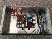
Like this, please check the thin red (+) and the thin black wire. Takes a few minutes (not months I hope ") ), no added cost. The power LED stops glowing when the amplifier gets too hot.
), no added cost. The power LED stops glowing when the amplifier gets too hot.
* You don't see a series resistor as that is built in with this particular green LED. I think it is a 12V version working perfectly on 5V with just enough brightness. 5V/12V LEDs are nonsense, they just have the series resistor built in as some have trouble with the LED formula (which is Ohms law really).
), no added cost. The power LED stops glowing when the amplifier gets too hot.* You don't see a series resistor as that is built in with this particular green LED. I think it is a 12V version working perfectly on 5V with just enough brightness. 5V/12V LEDs are nonsense, they just have the series resistor built in as some have trouble with the LED formula (which is Ohms law really).
Attachments
Last edited:
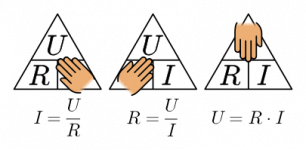
Ohms Law... the most necessary formula in electrical matters. Practice this just a few times with 5V, 9V, 12V etc. so you know how it works. In the LED case the LED has an Uf or forward voltage which you distract. So in case Ubatt is 12V and Uf of a normal green/amber/red LED is around 1.8V and desired result is a dimmed LED at 2.5 mA then:
(12 - 1.8)/0.0025 = R series = ?
With blue (terrible!), pink, purple, white LEDs Uf is higher so check their properties beforehand. Now at a certain high voltage things go slightly off like with 240V DC to a 2.5 mA LED. 240 - 1.8/0.0025 = 95280 Ohm. The series resistor will dissipate I x I x R= 0.59W! That will be a hot resistor. No issue with the usual low voltages.
BTW we say "U" to voltage here as we think that is cool. It was originally that way too.
Attachments
Last edited:
Good! I saw you posted another post speaking of "+ side" of LEDs. Please use the standard lingo like anode, cathode and write values like 5V, 2 mA etc. Volts and Amperes are in capitals so 5V, 1A etc. It makes people think when one does not even know how to write stuff AND wants help. Kind of respectful to write correctly.
So... eventually you got it covered like in post #44? This was already mentioned March 19th 2021....Stubborn is the right word
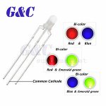
Now if you read the datasheet carefully you will see an "overcurrent LED" can be connected about the same way as the power on LED/Thermal LED. If you play very loud and the amplifier overheats the power on LED will stop glowing indicating the amplifier is overheating. This tends to be forgotten. For true LED porn you could combine the 2 functions with a bicolor LED with common cathode and both OC/Thermal pin high so both 5V under normal circumstances. The LED will emit the 2 colors mixed, in the case or a red/blue bicolor LED the light will be purple. When one of the error situations occur either one of the anodes will be pulled low and the LED color will change. Yes that also means 2 series resistors. Thermal could be terrible blue light, overcurrent could be red light in that case.
So... eventually you got it covered like in post #44? This was already mentioned March 19th 2021....Stubborn is the right word
Now if you read the datasheet carefully you will see an "overcurrent LED" can be connected about the same way as the power on LED/Thermal LED. If you play very loud and the amplifier overheats the power on LED will stop glowing indicating the amplifier is overheating. This tends to be forgotten. For true LED porn you could combine the 2 functions with a bicolor LED with common cathode and both OC/Thermal pin high so both 5V under normal circumstances. The LED will emit the 2 colors mixed, in the case or a red/blue bicolor LED the light will be purple. When one of the error situations occur either one of the anodes will be pulled low and the LED color will change. Yes that also means 2 series resistors. Thermal could be terrible blue light, overcurrent could be red light in that case.
Attachments
Last edited:
I went to wire the 125asx2 modules and discovered pin 3&4 are not included in the wiring harness. I depinned some other connectors I had that were also the same size wire and connector, and inserted it for pin 4...it worked perfectly. I then proceeded to do the other 5 amp modules and none would work. I even swapped 3 of them with the one that worked to see if it might be my repinning job...nope only 1 works. All of the amp modules work flawlessly for audio, but only 1 will drive a LED.
I looked online and all the wiring harnesses are missing the same 2 wires mine are...is it likely that I got a different version of the board that just so happens to have the feature, and the rest do not? I tried measuring the voltage, but was unsuccessfull on all the boards including the one that works. The way I was measuring was...red wire on my Fluke to the thermal pin, and black to the ground pin on the aux power. Meter set to DC voltage.I tested the bulbs with resistor with my adjustable DC power suppl and the bulbs work fine.
Has anyone been successful on doing this with the 125asx2? I thought about ordering some from Ghent Audio as they will populate the whole connector, but it will take over a month to get them in to rewire..Parts Express, but they do not carry the wires either, so no quick solution. The only other solution would be to eliminate the connector and hook up heatshrinked pins to each pin and retest.
Last edited:
- Home
- Amplifiers
- Class D
- Convert 120v to 12v for LEDs