1st of all: my main speakers are floor standing Focal Electra - should I ask someone to insure the cost of these guys for any amp's failure?
2nd: I removed "gold" capacitors and took a picture with original Nichicon caps that I bought on Mouser.
3rd: same for the opamps
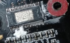
4th: seems like TPA3255 IC soldered by hands and not so good. White substance feels like caulk!
Please dont hesitate to guess, which opamps are original")
You took 0.47 uF capacitors ... the original ones are 10uF ... You risk losing in the reproduction of the bass...
Cool, you catch the difference! I put .47uF to compare with Chinese caps, not going to install those.You took 0.47 uF capacitors ... the original ones are 10uF ... You risk losing in the reproduction of the bass...
Let me explain:Hi,
Thanks for sharing pictures.
It is obvious that the welds are done manually ... Regarding the thermal paste, it seems a bit messy (I imagine, however, that having disassembled the heatsink must have spread it).
Did you give a try with the new caps finally ?
I suppose if you unsoldered the Nichicon FW from the buffer it is because you had a doubt about their authenticity? And the same goes for the OP amps since you seem to replace them with the same 5532 ...
keep us informed when you have tested the module with the new assembled components to know if there is any better?
1. White substance is NOT thermal paste. It's kind of caulk to keep TPA IC in place or so.
2. The opamps were NOT original, compare to sourced at Mouser.
3. I'll try to figure out what's wrong with my board and keep results posted.
....White substance is NOT thermal paste. It's kind of caulk to keep TPA IC in place or so.....
The White substance looks a little like RTV Silicone
Attachments
The White substance looks a little like RTV Silicone
Right. My point is what's reason to use it? Heatsink uses the screws to hold in place, TPA chip should be soldered etc.
The other picture of the amps boards doesn't have signs of this adhesive.
Right. My point is what's reason to use it? Heatsink uses the screws to hold in place, TPA chip should be soldered etc.
The other picture of the amps boards doesn't have signs of this adhesive.
Its common to put this adhesive around SMPS components to keep them from moving around. Often these products are shipped in a container on boat for a few weeks & they get shaken a lot. The Mfr does not want anything coming loose or breaking a solder joint.
See this tear down of a Siglent SDS2000 series oscillocope. There is goop on the SMPS components: EEVblog #1309 – Siglent SDS2000X Plus Scope Teardown+Hack – EEVblog
Also Apple TV circuit board: White glue on circuit board
Siglent SMPS, below....
View attachment 928655
View attachment 928656
Guys, are you serious?!
all pictures simply show caulk on trough-hole components instead of tiny SMD chip on mine photo. The reason to use the caulk/adhesive/whatever - to fix big chunky part in place and/or additional HV protection. However, I'm not PCB design professional like each other in this discussion, I just have some engineering background.
This silicone was under the bolted down heat sink? Does it wobble, when bolted down on this board?
There is no silicon on the board I purchased as seen by the photo.
It is quite clear these boards are assembled by hand. They don’t appear to have gone through a solder flow machine. Even the SMD components and the main TPA3255 chip appears to be hand soldered.
So I am guessing there may be a little gang of people assembling these boards and each will do it in their own way.
It appears your board may have the spacer washer also “glued” in place with the silicon. Maybe this was to ensure the heat sink didn’t short out the SMD components under it. There does appear to be quite a lot of solder on some components. Probably just a quick fix !!
So for we have 9 pages of comments and some other non-relevant stuff on this thread but very little about Sound Quality and Upgrades !!
Still waiting for my order for upgrade components from Mouser to arrive - They ship everything from the US so it takes time !! Also some of the Electrolytic’s I ordered were out of stock so still not going to be able to upgrade as I intended until these parts arrive.
.
Attachments
I have experimented a lot with the TPA3116 amplifier in the past. I came to the conclusion that a capacitance multiplier and a regulated power supply are beneficial. The lower voltage always resulted in a smoother sound. The situation is similar with the TPA3255 amplifier. We tested with a friend for hours yesterday and I can tell you this is one of the best sounding amplifiers I have ever had. (Various Pass Class A, Hiraga Le Monstre, JLH, Penasa Myref rev C, Tripaths, TPA3116 (8), etc.) Plays with extraordinary dynamics, musicality, liveliness. The stage is huge, with excellent separation and details. The capacitance multiplier is very sensitive to the capacitor. I use paralell 2x100uF Panasonic FCs. The supply voltage after the smps is now 29v and the sound with this solution is the most favorable for me. I think this amp is a good starting point for most diyers.
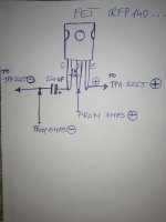
Hi Zek, I hope you understand the wiring diagram. It’s a very simple multiplier, but for me it gives the best sound.
Thanks a lot.

@Daniboun
On your posts in the big 3255 thread, you talk about swapping the big caps and how they can't be bigger than 20mm. I could only find 22mm KW ones both at Mouser and Digikey. Are those the ones you mean or am I missing something?
Blocked
The standard Caps that come with the board are 18mm in diameter and 31mm high. Height for the replacements is only dependent on your case !!
Certainly on my board you would not get a 20mm Capacitor between the heat sink and the Inductors !! Depends on what position the Inductors have been soldered - On mine they are towards the heat sink !! If you moved the Heat sink over a little towards the input side then you might just squeeze a 20mm Capacitor in this space but it would be very tight and of course be touching the heat sink.
You are probably not looking to increase the capacity - just a quality Low ESR Capacitor to replace the basic Nichicon VZ series that are installed by default. Maybe just bypassing the existing ones would be enough but as no one has yet done this comparison we don't know.
Options:-
Bypass existing Capacitors. (See what Claude did with the Aiyima A04).
Replace existing Capacitors with better low ESR ones.
Replace and bypass existing Capacitors.
I am in the process of doing much the same !!
Thanks Bushellj!
I ordered the boards just the other day so it'll be a while until I can have a look at them. I asked because Daniboun wrote that he had replaced them with Nichicon KW 4700 63V that measured 20mm. I'll check the Ayima 04 tweaks and follow this thread until I get the boards.
I ordered the boards just the other day so it'll be a while until I can have a look at them. I asked because Daniboun wrote that he had replaced them with Nichicon KW 4700 63V that measured 20mm. I'll check the Ayima 04 tweaks and follow this thread until I get the boards.
Hi,
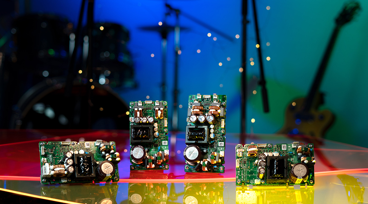
So you can compare VS the Shui Yuan :
Just got my new TPA3255 by HanZao.
This module is pretty unknown so I wanted to test it )
Out of the Box the module comes with the below components :
- 8000uf Rubycon YXF serie Low ESR / 50V
- Buffer caps, Rubycon YXF serie as well
- FIlm caps (MKP) Wurth
- SE Input (using Micro JST connector 2.0)
- DIP 8 OP Amps 5532 (updated with OPA1656)
Need to make a listening test before comparing vs others...
But sounds good at the moment. No Pop sound ON / OFF.
The module is really well protected : Yesterday I was tired and I mounted the power supply in the wrong way and the same for the OP amps... The module has automatically put itself in protection mode.
The Micro JST 2.0 connector is not practical for the SE input but I connected it with a JST 2.54 which is more conventional.
The amp :
- Full alu case
- HanZao TPA3255 module
- 350W LLC PSU / 36V / 9.5A
- OPA1656
- Alps volume pot
- PET Cooper Cables
- AC Filter
Next step : updating Buffer caps.... If I have time )
Hi Zek, I hope you understand the wiring diagram. It’s a very simple multiplier, but for me it gives the best sound.
What kind of resistor do you use?
I'd like to offer some advice on finding the fault on your amp Vincepgh.
1. The amplifier turns on therefore you can not have shorted power capacitors. The psu would turn off or burn up if thats were the case.
2. You don't have sound in either channel or hear thump in either channel. That means none of the channels are working or the TPA chip is simply turned off. Thumps occurs if thers a speakers short or the chip itself "senses that something is out of spec". Make sure the voltage is below 48V. Above ca 53V the chip itself shuts down and since many transformer psu deliver much higher voltage than spec'd on low loads that can often be the culprit. Then measure the voltage out from the step down voltage regulator that drive the op amps. There have been instances were chinese manufactures have used the wrong regulator. Also google the number to see if the regulator used is the right version.
3. Make sure you understand SE/balence jumper setting on your board. I assume it has such a jumper since my orignal 3e audio board has a jumper for type of input selection.
4. Make sure the opamps are inserted the correct way.
5. If none of the above steps solved the problem its probably a fault chip or bad soldering on the TPA3255 pins itself. It is possible to scrape/cut off excess solder with a safety razor blade to remove a short between pins. By making multiple cuts between the pins the solder can be cut away. See the tpa3255 datasheet for which pins that should be soldered together or get someone here to give you a photo of a working chip.
I hope this helps to clarify the situation and I belive the chalk has nothing to do with the amp not working. Just make sure the heatsink sits level on the chip and the volume is turned all the way down when you power it on. An overheating issue should take 1 minute or more to show itself, so that's propably not the issue here. The speakers/load should also be connected when applying power to the amp since its class D. I would use some cheap speakers for fault testing.
I also made some errors when connecting the 3e audio boards for the first time but it turned out I had a speaker terminal short (my mistake) and the jumper setting wrong. These boards are usally pretty hard to kill thanks to TI's protection design
- Home
- Amplifiers
- Class D
- Shui Yuan Audio TPA3255 Modification Thread