When I write "TPA3116" I mean "TPA3116D2". I have not known the previous TPA3116.
Thanks for the reference to 3126 modulation. One day I will set up one of my many TPA3116D2 boards directly on the load and bypass the output filter. With my oscilloscope it should be possible to get an idea about what kind of modulation the TPA3116D2 uses and why it can operate straight into the load.
In your case, if it works and no excessive current is drawn, if the TPA3116D2 chip does become suspiciously warm and it sounds good, just go ahead. I may use your results one day.
I can already conclude that I have far less knowedgle about class D topology that most guys here, but I'd like to tag along for this ride if that's ok. I am working on a similar project, and have made my own pcb design for an active analog Linkwitz-Riley crossover and preamp. For the next phase I was planning a filter less Tpa3116d2 design, but now I am tempted to look into the tpa3126 chip. I would very much be interested in the pcb design files if you would be willing to share them
I definitely recommend that you try the 3126 chip, it’s a pretty big improvement over the 3116, and so cool that it doesn’t even require a heat sink (at least for my modest desktop system). I’m happy to share the board I designed. Like I said before, I’m making some tweaks to better isolate the analog and switching power inputs, I’ll make extras since there seems to be some interest in it. Do you have experience soldering surface mount components? Also the 3126 chip can be challenging to solder, but it’s doable with a fresh tip and flux. Regarding the electronic signal-level crossover, I use the Elliot Sound Products 4th order L-R board which works great. Also, for the preamp take a look at the Warpspeed design, it’s a remarkable attenuator and bumped my system to a whole new level!
I’ve been experimenting with the TPA3126D2 in filterless mode and am blown away by the results. Because it runs so cool I use them directly connected to the speakers in the enclosure so no need for speaker cables. While I know some folks worry about RF emissions, I’ve designed the speaker enclosures as grounded faraday cages to contain any possibility of becoming an unintentional radio station!
I’m wondering if others have experimented with some of the newer class-d amps in filterless mode. If anyone is interested I’m glad to share details and a PCB I’ve designed to minimize the layout size as well as provide extra power filtering and isolation of analog/switching power.
I used some of the older i2s input 20w TI chips with BD modulation (Minidsp miniamp boards), with output filters removed,on my diy 3-way open baffle speakers and got similar results. Worked reliably except the tweeter did get warm. Fortunately it was a Beyma CP21 so could handle a bit of heat. I used Kimber twisted pair hookup wire as speaker cable, no problems with RF.
Cheers,
Mike
Glad to see you had similar results, it’s too bad that Class-d gets so little respect
 although there are lots more commercial class-d amps out there now that are getting good reviews.
 From my experience, going filterless, separating the analog and switching power sources (easy with the TPA 31XXD2 family), adding lots of low-capacitance (high frequency) power filtering (for both sources) very close to the chip, using an output snubber, and connecting with very short, or direct connections to the driver, allows class-d to really shine. If more people experimented with filterless modern class-d they’d be surprised at the quality sound produced.
I guess it’s reasonable to expect a tweeter to get warm, it seems very dependent upon the driver and how much impedance you get a high switching frequencies, you just have to experiment. The 2” driver I’m using on my desktop system covers from about 180Hz through to 20kHz and as I mentioned before stays very cool. My signal-level electronic crossover is 4th order so doesn’t send too much lower frequency signal to the small drivers, which resonate at about 90 Hz.
I’m curious how long your speaker cables are? Have you done any quantitative tests for RF emissions?
Quantitative test? Well, zero out of 3 neighbours complained... actually the main test was to see if my phono stage was affected. So no. Speaker cables were/are about 2m long.
Agree with your further comments, I run a linear choke-input LCLC power supply with Lundahl filament chokes, all modelled and optimised for transient response with no overshoot. Weighs a ton and sounds great.
Cheers,
Mike
Agree with your further comments, I run a linear choke-input LCLC power supply with Lundahl filament chokes, all modelled and optimised for transient response with no overshoot. Weighs a ton and sounds great.
Cheers,
Mike
It's a shame you can't have a DAC and class d chip all in one, so there would be no analogue in the middle. If class d sounds so much better without an output filter, wouldn't it be an idea to fine out how the output filter could be improved, rather than omitting it all together ?
I only know of one IC with I2S input and class D filter-less output. The MAX98357 from Maxim. Not much power. There may be other.
On the output filter - I am pretty sure the class D chip manufacturers did that during the last 20 years. It is in their obvious interest.
NB: Maxim has more such class D amplifiers. ST may also have.
On the output filter - I am pretty sure the class D chip manufacturers did that during the last 20 years. It is in their obvious interest.
NB: Maxim has more such class D amplifiers. ST may also have.
Last edited:
Last edited:
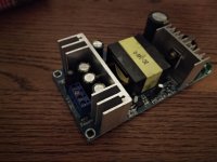
I have the same type SMPS with varying output voltages.
You can use an SMPS in front of a linear regulator, instead of a transformer. Like this, you avoid having the voltage reduction with higher loading that characterizes the transformer such that you can do with a 3-4 volt difference from the input and to the output of the linear regulator. But, the output voltage will be maximum 20-21Vdc. With a linear post-regulator you can achieve better noise and load-regulation performance. An SMPS is often cheaper than a transformer. The SMPS unfortunately produces some noise at higher frequencies.
You can make a better output filter to reduce noise further.
Really big design changes of an SMPS is difficult because the SMPS transformer is designed (optimized) for a particular use.
You can change the output voltage a little but not a lot without loosing output power and perhaps reliability.
- Status
- This old topic is closed. If you want to reopen this topic, contact a moderator using the "Report Post" button.
- Home
- Amplifiers
- Class D
- Filterless Class D with TPA3126D2