Good thing i have a spare, but it is some work to do the updates.
I feel your pain. What happened to C16 and C23? C10 & C11 are the pos and neg inputs for the left channel (PBTL input according to datasheet) - did you remove C11 and attach straight balanced negative?
A ground wire is missing from the balance input.
Not needed when all boards share the same ground.
C11 is an optical illusion. There is a cap there but it is in the axis of the camera so it just looks like a solder blob ")
The stupid thing about that board is that it LOOKS like C16 and C23 are for the left channel, but the left inputs are tied to ground (consistent with what the copy of the datasheet that I have says to do for PBTL.)
C16 and C23 are actually connected to the PLIMIT and GVDD pin (??? huh?), so they used a pair of huge electrolytics just to decouple GVDD. I initially changed them to the same ceramics that I used for the input caps (3.3uF, not perfect but what I had around). The board worked fine. (this was the configuration I had since the beginning)
Then when I did the update to balanced/differential (I know they're not strictly the same but not sure what this setup technically is) I changed C16 to 1uF like in the datasheet and removed C23 because it seemed redundant to me.
Gave it some power and Poof! I released the magic smoke.
I did something similar with two TPA3118 and one TPA3116 amps. I used isolated DC-DC converters and balanced connections from the DSP.
Have ytou snooped around for ground loops? If the two amps share the same power ground then they don't need both signal grounds connecting. That will cause a loop.
The advice given to me was to take it apart (disconnect) everything and put it back together ensuring each device works as it should one by one. Then maybe in different orders.
I too used the Arylic board but found it annoying and noisey so my friend opted for an Echo Dot in the end.
Are you using the line in on the Arylic? I found that very noisy and didn't like sharing the audio ground with anything else.
No, actually I'm only using the arylic for the USB/DAC input and the airplay over wifi.
I'm going to get a couple of those isolated power supplies for the Arylic and the DSP. By process of elimination, the main offender is clearly the Arylic. but I'm powering it from a tiny 24v->5v switcher module. It does still make the sound when I power it externally (keeping the ground connected.. i forgot to test without the ground)
C11 is an optical illusion. There is a cap there but it is in the axis of the camera so it just looks like a solder blob
C11 still there so it's not balance circuit, there's still ground loop.
Is the wire after C11? Ground signal directly to IC pin?
Thanks for the photos, Brian.
If it works well after the many good advises you have gotten until now - fine. If not, you have followed a procedure that often leaves noise issues.
You cannot just put noise-sensitive circuits (the TPA3116 inputs among other) close together with digital circuits and assume you will have no noise-coupling.
A more systematic way would be to arrange all the boards with good distance and make sure the system works like that. Here you can get rid of wire-carried noise. After that, you mount the two TPA3116 boards in the cabinet and check-out if that still leaves no problems, Then, the next-most sensitive board and test. Following such a procedure you will notice which boards cause most trouble.
Putting all together for a start and realizing that you have unacceptable noise, leaves you no knowledge of if it is due to conduction or radiation and which boards are the most problematic. You work in the haze when trying changes around in the system.
VERY nice! I was just doing this when I saw the post here.
Thanks. I actually have everything apart now spread out on the bench and I will put them back one at a time.
I also found another TPA3116 board that has a NE5532 (in a socket so I can swap it for a genuine one of I need to) and a volume pot.
https://www.amazon.com/gp/product/B07H337F4L

Do you guys have any experience with this board? It might be too large to fit in my enclosure, but it looks easy to mod if the layout is decent. (although honestly, i prefer surface mount components from a practical standpoint)
What do you think about my idea of using a single-sided bare copper PCB as a base to mount the boards to (copper side away from the boards, naturally)?
My thought was to use the copper as a ground plane (and power ground) and drill holes for the power and non-signal wires to go below it. This way each board would have a short ground wire leading to the copper. Similar in concept to using a car's chassis as the ground in a car.
Thanks. I actually have everything apart now spread out on the bench and I will put them back one at a time.
I also found another TPA3116 board that has a NE5532 (in a socket so I can swap it for a genuine one of I need to) and a volume pot.
https://www.amazon.com/gp/product/B07H337F4L
Do you guys have any experience with this board? It might be too large to fit in my enclosure, but it looks easy to mod if the layout is decent. (although honestly, i prefer surface mount components from a practical standpoint)
What do you think about my idea of using a single-sided bare copper PCB as a base to mount the boards to (copper side away from the boards, naturally)?
My thought was to use the copper as a ground plane (and power ground) and drill holes for the power and non-signal wires to go below it. This way each board would have a short ground wire leading to the copper. Similar in concept to using a car's chassis as the ground in a car.
Last edited:
Hi Brian,
If you have connections that are clearly "power" then use the ground-plane (evidently).
If you have connections that are only signal then use separate wire connections.
If you have connections that are a mix of signal and power, then use the ground-plane and rely on its very low impedance. The last cattegory should include your DSP.
Last edited:
AH, interesting. good. so then the (-) signals between the source and the DSP (single-ended) go through the ground plane. That was definitely the connection that was causing the interference before actually.
The pins that connect to the (-) signal ground on those boards are indeed just tied to the ground plane anyway. That sounds like a reasonable explanation for some of the interference.
Then the signal connections to the amps (differential) would not. Perfect. This is much more logical.
Cool, I'll make the updates this morning. Just finishing up the mods on the replacement board.
Thanks
Yes, sorry, I am all over the place with my terminology (I'm a scientist, not an EE, so I don't know alot of the specific terminology. Definitely gets me into trouble with folks who know the art.
I am referring to signal ground. I can't kick the habit of always referring to signal ground as (-). Definitely a bad idea when there are differential signals in the mix!
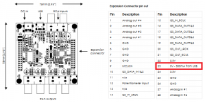
This is the DSP board (disregard the red square, not my image). I will be using pins 27 and 28 for the input from the source (no signal grounds) and using 3-6 for the start of the differential signal chain.
I've got that pre-amp for the sub signal that I will be using single-ended from the DSP but then differential to the amp.
I am referring to signal ground. I can't kick the habit of always referring to signal ground as (-). Definitely a bad idea when there are differential signals in the mix!
This is the DSP board (disregard the red square, not my image). I will be using pins 27 and 28 for the input from the source (no signal grounds) and using 3-6 for the start of the differential signal chain.
I've got that pre-amp for the sub signal that I will be using single-ended from the DSP but then differential to the amp.
Attachments
Last edited:
Many thanks, Brian.
Just to get on the same wave-length: It is a MiniDSP 2x4 board you use as a numerical programmable cross-over with the aim to have a stereo-channel and a mono sub-channel? You have removed the RCA connectors? If correct, please progress->
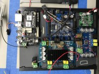
The fourth board I see on your photo of your system cabinet is a micro-computer (Raspberry PI or the like) used to feed numerical music information into the MiniDSP board? Or, is the input to the MiniDSP board also an analog signal which is sampled by the MiniDSP board, filtered and brought back to analog by DACs on the MiniDSP board?
Has it ever worked with reasonable noise/hum before you started putting everything in one cabinet?
Your two class D amplifiers are supplied from one or two power supplies? Your MiniDSP board is supplied from its own power adapter via the DC-plug? And, your micro-computer is supplied from yet another power-adapter?
Is it possible to pre-program the MiniDSP board such that the micro-computer is not connected when you test the MiniDSP with the class D amplifiers?
Just to get on the same wave-length: It is a MiniDSP 2x4 board you use as a numerical programmable cross-over with the aim to have a stereo-channel and a mono sub-channel? You have removed the RCA connectors? If correct, please progress->
The fourth board I see on your photo of your system cabinet is a micro-computer (Raspberry PI or the like) used to feed numerical music information into the MiniDSP board? Or, is the input to the MiniDSP board also an analog signal which is sampled by the MiniDSP board, filtered and brought back to analog by DACs on the MiniDSP board?
Has it ever worked with reasonable noise/hum before you started putting everything in one cabinet?
Your two class D amplifiers are supplied from one or two power supplies? Your MiniDSP board is supplied from its own power adapter via the DC-plug? And, your micro-computer is supplied from yet another power-adapter?
Is it possible to pre-program the MiniDSP board such that the micro-computer is not connected when you test the MiniDSP with the class D amplifiers?
Last edited:
Exactly right
The ‘source’ board is a up2stream by arylic Wifi Stereo Receiver For DIY Speaker | Multi zone Control-Arylic.com
– arylic
Unfortunately, the i2s signal (digital output) is not compatible with this miniDSP digital input, so you are correct that it needs to go analog first, then be redigitized. Not optimal, but that’s life.
Everything is powered from the same 24v supply, but the arylic is powered by an LDO making 5v from the 24v supply.
It is quite easy to test the signal path from DSP back. I have actually been doing that to narrow down the source of the interference coming from the mono amp (running in single-ended mode before i blew it up)
The stereo amp works perfectly, no hum or hiss (once i put it differential and reduced the gain). I replaced the mono amp, and it still has the interference even after cap upgrades (no improvement expected) and differential input mod. The interference comes even if the ‘source’ is not playing. It only needs to be connected to cause the issue.
I am almost done moving the boards to the new ‘ground plane’ setup. I’ll test it again then. I cleaned up the wiring and took extra care to keep power connections below the ‘ground plane’.
We’ll see! Thanks for the great advice!
I don't know why I didn't suggest this earlier but if you really struggle to get two amp boards working together you could always use a 2.1 board and bypass the onboard "crossover" that is usually implemented. That way (if theyhave observed the datasheet for manufacture) these problems might have been avoided.
However, I kinda feel like this needs to be done your way first!
Further, you can always bodge a balanced output from the MiniDSP by outputing two channels of subwoofer signal and inverting one channel for the hot and cold signal.
However, I kinda feel like this needs to be done your way first!
Further, you can always bodge a balanced output from the MiniDSP by outputing two channels of subwoofer signal and inverting one channel for the hot and cold signal.
Once more a good idea from Graham.
My suggestion is that you first try-out what you are currently doing. You are generally doing pretty well for a non-electrical engineer.
If you do not succeed, my remark would be that the MiniDSP has not been designed with two RCA input connectors and four RCA output connectors knowing that it would not perform well without converting it into balanced signal transfers. Balanced signal transfer is a way to give the fine polish to a signal chain and improve the non-balanced performance a little. Not the only way to make it function. In other words, it should be possible to make it work quite well without changing into balanced signal transfer with the modifications that entails. It is probably a matter of testing the components connected one-by-one and hum-problems may relate to the use of more power supplies.
I will await the results of your current work.
Thanks. I was an analytical chemist PhD so i’ve had my hands inside instruments and electronics forever. I still build alot of prototype systems, but the components, modules, etc are usually of significantly higher quality than i’ve been dealing with here. Most of my electronics experience was from making chemical weapons detectors for a defense contractor. Lots of ‘on the job’ learning from EEs that used to make spy satellites. So I find that my first instinct is overkill, then i have to come back to reality
The fake ‘differential’ signal transfer, just using the signal ground at the source as the negative signal and using twisted pair wires is an old car stereo trick. Since a significant portion of the noise is collected on the signal lines, having the twisted pair and differential input at the amp actually makes a significant difference.
Unfortunately you always end dealing with level mismatches so gains can be funky.
I have actually had the stereo amp working nicely all along (aside from the hiss). We will see this morning!
- Status
- This old topic is closed. If you want to reopen this topic, contact a moderator using the "Report Post" button.
- Home
- Amplifiers
- Class D
- NE5532 Preamp unused channel termination?