D
Deleted member 148505
@JLesterP: Do you really think that limiting the high frequency response beyond the range of hearing can give a positive effect? What is the nature of this effect?
We are adding feedback cap to increase stability. I used significantly smaller cap value compared with SLAA788A implementation. You can add up to 180pF to match SLAA788A.
D
Deleted member 148505
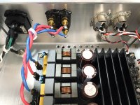
Sylph-D200 V1 users: you can replace GVDD (C11, C16) caps with 1uf 35V tantalum. The caps are beside the TPA3255 IC.
T491A105M035AT this is what I'm currently using on my best sounding module.
V1P users: currently comparing side by side with V1.
Current version is V1P2 which is based on V1
T491A105M035AT this is what I'm currently using on my best sounding module.
V1P users: currently comparing side by side with V1.
Current version is V1P2 which is based on V1
Last edited by a moderator:
D
Deleted member 148505
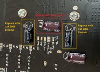
Found that some of our Sylph-D200 modules have Rubycon caps installed for GVDD (C11 & C16), it should be Panasonic FR (Rubycon was mistakenly soldered because they look similar and has same value). If Rubycon is installed, the sound is harsh. If Panasonic FR is installed, the highs will be smoother but the midrange will be thinner.
For Sylph-D200 (all versions), GVDD has a large impact on sound, if electro caps are used, the sound will be thinner. Replace the electro caps on C11 and C16 with 1uF ceramic caps 0805 SMT. (solder them on TPA3255 IC side) For Sylph-D200 V1: 10uF ceramic cap is currently installed, replace it with 1uF 0805 ceramic (or 1uF 35V 3216 tantalum).
For AVDD cap, 10uF Silmic II sounds the best for me. Currently soldered cap is Nichicon general purpose 100uF.
These should improve the sound for Sylph-D200 users.
Attachments
D
Deleted member 148505
D
Deleted member 148505
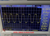
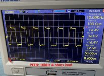
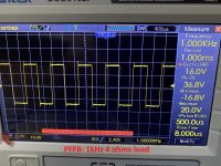
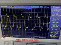
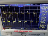
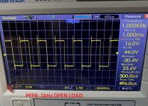
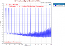
Sylph-D200 Square wave open load response
Some square wave 4 ohms and open load response of Sylph-D200
Power supply used: LRS-350-36 at 36VDC-ish
1st set: open load response
2nd set: 4 ohms load response
Disclosure: I already sent the amp to Amir, hopefully it will push through within 3 months. Unfortunately I (don't know) if I submitted it with rubycon or Pana FR electro caps on GVDD section. I've used 100uF nichicon on AVDD.
Hopefully the reported harshness with rubycon caps on GVDD will not translate to poor high frequency measurements.
I already compared all the modules with different parts, and the best sounding one belongs to a module with 1uF ceramic on GVDD section, and 10uF Elna Silmic II on AVDD.
Attachments
I made the recommended modifications by Lester, replacing the rubycon capacitors with ceramic ones and inserting the ELNA SILMIC II on the AVDD.
First impressions from listening after the modifications - I have a pleasure of listening to music. There is detail, plankton, good decay, air and dark background.
This is what I like.
And it does not make me tired.
So I will not go any further and I have no intention of putting capacitors in the opamps feedback. I remember the rule: less is better.
I made the recommended modifications by Lester, replacing the rubycon capacitors with ceramic ones and inserting the ELNA SILMIC II on the AVDD.
First impressions from listening after the modifications - I have a pleasure of listening to music. There is detail, plankton, good decay, air and dark background.
This is what I like.
And it does not make me tired.
So I will not go any further and I have no intention of putting capacitors in the opamps feedback. I remember the rule: less is better.
That sounds good. I can't wait to do the modifications too.
Do you have PFFB activated or not?
D
Deleted member 148505
So I will not go any further and I have no intention of putting capacitors in the opamps feedback. I remember the rule: less is better.
It is required for PFFB stability specially on open load condition, it will also remove some grit in high volume listening. (also applicable with other TPA3255 builds)
You can place 100pF to 180pF. The measurements above uses 100pF (78kHz opamp bandwidth)
It is required for PFFB stability specially on open load condition, it will also remove some grit in high volume listening. (also applicable with other TPA3255 builds)
Hi Lester,
Looking at the PFFB schematic shown in Application Report SLAA788A, we see that the buffer operational amplifiers are not affected by global amplifier feedback. Thus, limiting the bandwidth by adding a capacitor in the OPamp feedback should have no effect on the stability of the amplifier's no-load operation. Of course they improve the stability of the buffer, but on the other hand taking into account the filters used in signal sources (e.g. in DACs) it seems that capacitors are not necessary. Please point out the error in my thinking.
D
Deleted member 148505
Hi Lester,
Looking at the PFFB schematic shown in Application Report SLAA788A, we see that the buffer operational amplifiers are not affected by global amplifier feedback. Thus, limiting the bandwidth by adding a capacitor in the OPamp feedback should have no effect on the stability of the amplifier's no-load operation. Of course they improve the stability of the buffer, but on the other hand taking into account the filters used in signal sources (e.g. in DACs) it seems that capacitors are not necessary. Please point out the error in my thinking.
Purpose is to limit the gain at high frequencies. It will prevent high frequency instability at open load conditions since some users might input high frequency into the amp not knowing that the amp cannot handle it. If you are sure that there are no other high frequencies being injected into the system, then the amp will be fine.
D
Deleted member 148505
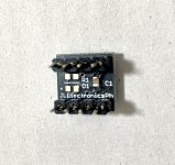
For Sylph-D200 users with LME49860 and/or OPA1656 opamps in DIP socket.
Kindly remove the 100nF capacitor under the adapter PCB. The capacitor is connected to pins 4 and 8 of the opamp. This bypass cap is ok with TPA3255 modules with single supply opamps since it will be connected to +12V and GND of the opamp supply.
But since our module uses split supply for the opamps, this cap is connected across +6V and -6V opamp supplies. I also identified this as the contributor to harsh sound (really), when I removed it, highs are now smooth (PFFB and non-PFFB smoothness are almost the same).
Unfortunately, the module that I've sent to Amir uses this opamp adapter and has rubycon caps on GVDD supply, so the high frequency measurements might get affected.
Regards,
Lester
Attachments
Last edited by a moderator:
D
Deleted member 148505
@JLesterP, Does the capacitor on the opamp pcb lead to the high frequency behavior seen in Amir's multitone test ?
No, multitone test looks normal in above average performing amps.
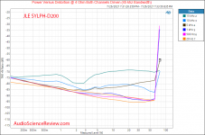
What's unexpected though is the low performance behavior of 15kHz in Amir's power vs distortion graph (45kHz bandwidth)
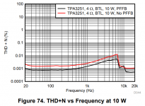
In SLAA788A document attached, 6.67kHz should have the highest distortion. (though the bandwidth measurement was not disclosed)
Regards,
Lester
Attachments
D
Deleted member 148505
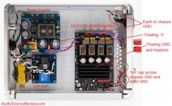
This is what I'll do with my Sylph-D200 build:
Use IEC connector for mains wire, then connect the IEC's earth to chassis. If the chassis is anodized, sand it off for better connection.
Same with the switching power supply, connect the earth to chassis, I think ground loop protection is built-in on the Mean well supply.
Make the Sylph-D200 float, for the RCA connectors, insulate them from the chassis, and connect a capacitor on each signal ground of the RCA terminals to the chassis.
Not earth the -V of the Mean Well.
This wiring actually worked as there are no large mains harmonics in the measurement.
Attachments
Last edited by a moderator:
")
No, multitone test looks normal in above average performing amps.
What's unexpected though is the low performance behavior of 15kHz in Amir's power vs distortion graph (45kHz bandwidth)
In SLAA788A document attached, 6.67kHz should have the highest distortion. (though the bandwidth measurement was not disclosed)
Regards,
Lester
Doesn't the distortion profile in SLAA788A imply that the measurement bandwidth is 20kHz? This is consistent with Amir's measurements (3rd harmonic dominates).
Cheers,
Mike
D
Deleted member 148505
Doesn't the distortion profile in SLAA788A imply that the measurement bandwidth is 20kHz? This is consistent with Amir's measurements (3rd harmonic dominates).
Cheers,
Mike
Yes correct, the datasheet's measurement bandwidth is 20kHz so it implies that SLAA788A's the same. After 6.67kHz, 2nd harmonic is the dominant contributor, then after 10kHz only the noise is being measured.
I've checked other TPA3255 and their power vs distortion at 45kHz bandwidth is similar.
When I measured the amplifier while it's hot, the 2nd and third harmonics are the same, I will try to repeat it again to verify. Post #254, amp is cold and 3rd harmonic dominates. Post #267, amp is hot.
Anyhow using a low THD+N preamp or buffer with a dominant second harmonic will shape the harmonic outcome. So what's important is that we have an amp with a flat freq response, good crosstalk, good baseline noise + distortion profile even with high power, then after that you can shape the sound or add flavor depending on preamp used.
- Home
- Amplifiers
- Class D
- JLE TPA3255 Build and Modifications