Honestly, you should just temper your own expectations a little bit. daniboun is out here working hard for all our benefit and you are looking the gift horse in the mouth.
He never mentioned anywhere that he is a certified golden-ear listener with an accredited reference system. If you can't extrapolate his feedback into anything useful for yourself, just ignore what he says and carry on... for myself, I appreciate the work even if it doesn't necessarily match up with quantifiable measurements.
Hi thanks, do not worry, I spoke with TNT. He did not read that I shared my setup in my review. I can easily understand that some users need concret measurements and precise analysis method to give a credible value to a review
In any case, I would continue to share my experiences with the greatest pleasure and with a good heart) thanks again )
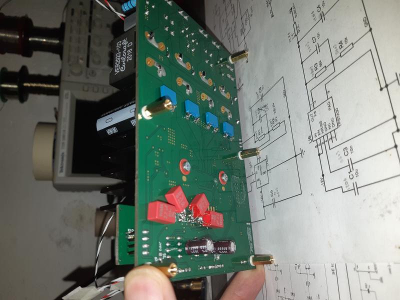
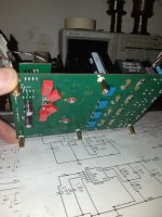
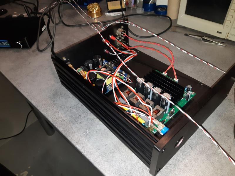
New PCB arrived and wired !
It rectifies wrong pads (SOIC8 instead of VSSOP).
It tuned a bit some feedback caps, replace Muse caps for MKT (1+2.2=3.3uf for each input), adjusted common mode of the OPA1637 to null DC offset across them, added some 0.1uF MKT 7.5mm spacing for each 2000uF caps.
Finally, the sound is amazing compare to "original" JLE board with my small Eltax in the garage.
I will build the overall amp soon and test in my living room with real speakers (SB Acoustics DIY).
D
Deleted member 148505
Weren’t you going to drop C5-C8 to 22pF (from 100pF) or did I read that incorrectly?
Pete
I will try to remove them first and check for stability, if found stable then I will remove them in my new module (and use solder bridge). Default is 100 ohms + 22pF, which is now being manufactured)
D
Deleted member 148505
Wow congrats! A good differential buffer is the key to a good sounding TPA3255 ") I think you are the first to use OPA1637 for TPA3255 if I'm not mistaken.
I think you are the first to use OPA1637 for TPA3255 if I'm not mistaken.
Replacing PFFB parts with C0G and low ppm matched resistors I think will have a measurable improvement on THD.
3.3uF is just right for 20K ohms input impedance of TPA3255, there is really no space for a Wima MKT on my 150x100mm board.
(reattaching your jpg so that it won't get lost in the future)
I think you are the first to use OPA1637 for TPA3255 if I'm not mistaken.Replacing PFFB parts with C0G and low ppm matched resistors I think will have a measurable improvement on THD.
3.3uF is just right for 20K ohms input impedance of TPA3255, there is really no space for a Wima MKT on my 150x100mm board.
New PCB arrived and wired !
It rectifies wrong pads (SOIC8 instead of VSSOP).
It tuned a bit some feedback caps, replace Muse caps for MKT (1+2.2=3.3uf for each input), adjusted common mode of the OPA1637 to null DC offset across them, added some 0.1uF MKT 7.5mm spacing for each 2000uF caps.
Finally, the sound is amazing compare to "original" JLE board with my small Eltax in the garage.
I will build the overall amp soon and test in my living room with real speakers (SB Acoustics DIY).
(reattaching your jpg so that it won't get lost in the future)
Attachments
New PCB arrived and wired !
It rectifies wrong pads (SOIC8 instead of VSSOP).
It tuned a bit some feedback caps, replace Muse caps for MKT (1+2.2=3.3uf for each input), adjusted common mode of the OPA1637 to null DC offset across them, added some 0.1uF MKT 7.5mm spacing for each 2000uF caps.
Finally, the sound is amazing compare to "original" JLE board with my small Eltax in the garage.
Nice update and impressive ! Congratulations !
OPA1637 is a fully differential op amps right ? I saw someone shared some measurements via a balanced twin-tee :
Last edited:
I tested my DAC in PC-USB and bluetooth and unfortunately the level in bluetooth is not very high. I do not know why ...
Max level in BT : 2.76vpp (0.973Vrms)
Max level in PC-USB (with REW) : 7.48Vpp (2.64Vrms)
Then, i d like to add some gain but as Lester warned me, i have to protect the input of TPA3255 (7Vpp).
Two ideas. First one is a low cap TVS but difficult to clearly stop the voltage (because depends of the current).
Second, down the supply voltage with a R(RA7)+zener. Should be better. Problem is the rail to rail of OPA1637 is not precisely defined in the datasheet ...
D
Deleted member 148505
I tested my DAC in PC-USB and bluetooth and unfortunately the level in bluetooth is not very high. I do not know why ...
Max level in BT : 2.76vpp (0.973Vrms)
Max level in PC-USB (with REW) : 7.48Vpp (2.64Vrms)
Then, i d like to add some gain but as Lester warned me, i have to protect the input of TPA3255 (7Vpp).
Two ideas. First one is a low cap TVS but difficult to clearly stop the voltage (because depends of the current).
Second, down the supply voltage with a R(RA7)+zener. Should be better. Problem is the rail to rail of OPA1637 is not precisely defined in the datasheet ...
Have you checked if there's a limiter on your DAC like max 1Vrms? So that you can change the gain to 3 without worrying.
Also max input current of each input of TPA3255 at 7Vpp is 1mA.
D
Deleted member 148505
Yes, I will also try to remove R1~R4, C5~C8 next weekend.
Weren’t you going to drop C5-C8 to 22pF (from 100pF) or did I read that incorrectly?
Pete
Hi Pete,
I already tried to remove the R1-R4 and C5-C8 (RC filter) replaced it with a short, then 10pF C0G on opamp feedback caps.
Still the best sounding is no cap on feedback. RC filter (R1-R4 and C5-C8) does not have an impact on sound.
Maybe the opamp socket in my module is already loose and capacitative, so no need for opamp feedback caps lol.
Regards,
Lester
So, just to understand what you just said Lester, CA3, CA6, CB3 and CB6 are removed (for best sound) but altering R1-R4 & C5-C8 doesn’t really add any sonic benefits so just leave them be on my V1 board?
Loose sockets will get you in trouble all the time...
Thanks,
Pete
D
Deleted member 148505
So, just to understand what you just said Lester, CA3, CA6, CB3 and CB6 are removed (for best sound) but altering R1-R4 & C5-C8 doesn’t really add any sonic benefits so just leave them be on my V1 board?
Loose sockets will get you in trouble all the time...
Thanks,
Pete
Yes, correct. If you want to go full non-PFFB, you can short RA7, RA8, RI1 to RI4, it will have sonic benefits.
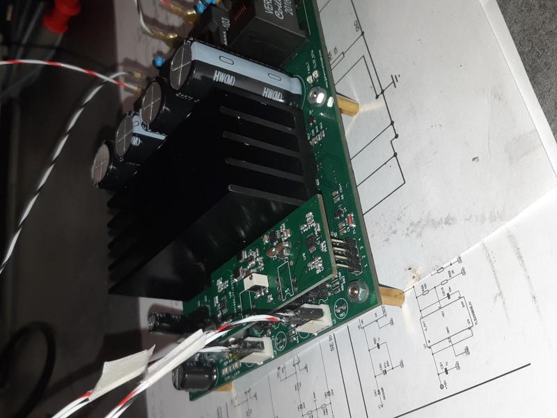
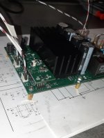
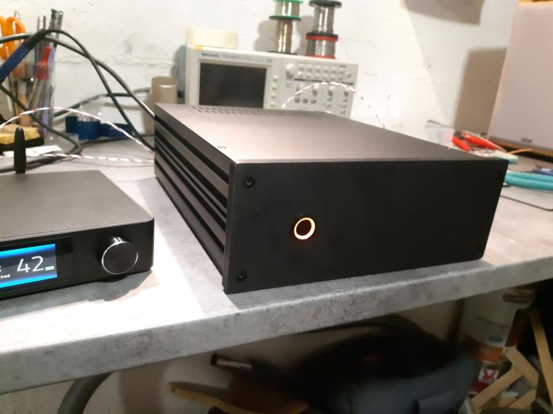
Amp is building.
Lester, the TPA board should not connected to the chassis via the screw, isn't it ?
You can connect the heatsink screw to the chassis. The whole amp module is floating, there's no connection from ground to standoffs.
Yes, correct. If you want to, you can short RI1 to RI4, it will have sonic benefits.
Something to try today..
Thanks Lester.
You will soon have nothing to try
BradP... I will be waiting for that.. I've used enough chip-quik & de-soldering wick on Ver 1
Pete
D
Deleted member 148505
- Home
- Amplifiers
- Class D
- JLE TPA3255 Build and Modifications