D
Deleted member 148505
Hello,
i have found on market cases similar to your assembled module. But all without cooling holes. Do you confirm that holes are not needed or holes are requested?
Hi Vito,
Holes are needed for better heat dissipation.
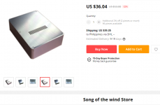
This is the exact case that I've used (song of the wind aliexpress), they always change the price but usually the range is 70 to 90USD shipped.
The front panel is real pain to drill because it's very thick! You need flowing water to avoid overheating the step drill bit.
Regards,
Lester
Attachments
D
Deleted member 148505
Hi Lester!
What's a good output impedence range for dacs or preamps feeding this amp I wonder? I'm planning to use a very low (10 ohms) impedence preamp (Kenwood L-07 C II) with my Sylph-D200. I know lower is usually better but will this be ok?
Hi Chris,
Rules of thumb for a dac or preamp driving a load without getting voltage divider or other nasty side effects is to load it with 10x or more their output impedance.
So your preamp with 10 ohms output impedance can drive a load with 100 ohm input impedance or higher.
Since our module has 10K input impedance, we can use a source or preamp with output impedance of 1K ohm or less. Dacs usually have 100-200ohm output impedance so no problem.
Regards,
Lester
D
Deleted member 148505
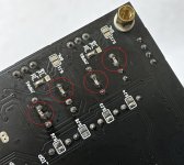
Sylph-D200 checklist
Here's a checklist to ensure that Sylph-D200 sound is optimal. (in order of importance)
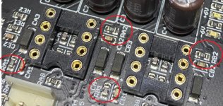
1. Make sure RA1, RB1, RA2, RB2 is 0 ohm, or shorted with a solder blob.
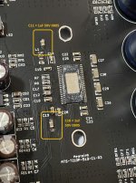
2. Change (C11, C16) GVDD caps from electro capacitors under the PCB, to a 1uF ceramic
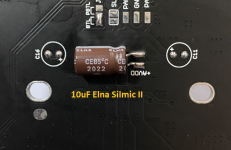
3. Change AVDD cap from 100uF Nichicon, to 10uF Elna Silmic II
4. Insert 47pF to 100pF C0G caps on pins 1-2 and 6-7 of opamps.
5. CS2 electro cap under the PCB can be replaced with 22uF Panasonic FR (placed on top of PCB)
PFFB has better highs than non-PFFB mode, however, some speakers are forgiving on their high frequency output. You can disable PFFB if your speaker's tweeter performance is good regardless of amp used.
Here's a checklist to ensure that Sylph-D200 sound is optimal. (in order of importance)
1. Make sure RA1, RB1, RA2, RB2 is 0 ohm, or shorted with a solder blob.
2. Change (C11, C16) GVDD caps from electro capacitors under the PCB, to a 1uF ceramic
3. Change AVDD cap from 100uF Nichicon, to 10uF Elna Silmic II
4. Insert 47pF to 100pF C0G caps on pins 1-2 and 6-7 of opamps.
5. CS2 electro cap under the PCB can be replaced with 22uF Panasonic FR (placed on top of PCB)
PFFB has better highs than non-PFFB mode, however, some speakers are forgiving on their high frequency output. You can disable PFFB if your speaker's tweeter performance is good regardless of amp used.
Attachments
Last edited by a moderator:
D
Deleted member 148505
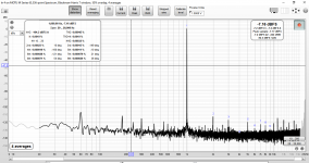
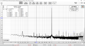
Been experimenting with PFFB values.
Latest values require 8pcs SMT 0603 changes in PFFB section, available for owners who want to tinker. The sound will remove some air and lowers down the high frequencies but the midrange will be as good as non-PFFB.
Attached THD spectrum 4ohms 5W and 10W (on 6.8uH coilcraft inductor). The noise floor is higher on this one compared to ASR because it uses 1.5X gain buffers and uses 48V supply. I will try to measure again with other modules using 1.3x gain.
Mains harmonics and high freq noise is due to 48V generic meanwell clone used in the setup.
Attachments
Last edited by a moderator:
D
Deleted member 148505
The attached measurements look cool. What wonders me is the reduction in odd harmonics distorsion versus second and fourth order harmonics. Especially since bridge amplifiers tend to reduce even harmonics. That negatively affects the subjective sound quality.
Yes, I will post spectrum profile up to > 100W 4 ohms later after the values have been finalized..
Erratum: The module that I've tested with snapshots above has 1.8x opamp gain.
D
Deleted member 148505
Been experimenting with PFFB values.
Latest values require 8pcs SMT 0603 changes in PFFB section, available for owners who want to tinker. The sound will remove some air and lowers down the high frequencies but the midrange will be as good as non-PFFB.
Attached THD spectrum 4ohms 5W and 10W (on 6.8uH coilcraft inductor). The noise floor is higher on this one compared to ASR because it uses 1.5X gain buffers and uses 48V supply. I will try to measure again with other modules using 1.3x gain.
Mains harmonics and high freq noise is due to 48V generic meanwell clone used in the setup.
After careful listening and stability testing, the latest PFFB config has been finalized (for 6.8uH output inductors only). Can be used with 36V to 48V DC supplies. And most importantly, now has undisputedly better sound than non-PFFB
")
Existing modules that use 6.8uH inductors require 13pcs 0603 SMT parts to be replaced (on PFFB section).
Applicable to TICore260BTL and Sylph-D200 modules that use 6.8uH output inductors.
After careful listening and stability testing, the latest PFFB config has been finalized (for 6.8uH output inductors only). Can be used with 36V to 48V DC supplies. And most importantly, now has undisputedly better sound than non-PFFB
Existing modules that use 6.8uH inductors require 13pcs 0603 SMT parts to be replaced (on PFFB section).
Applicable to TICore260BTL and Sylph-D200 modules that use 6.8uH output inductors.
Hello
Good news.
Can we see the frequency response / 8 ohms and a square wave / 10kHz
Thank you
Best regards
Roger
D
Deleted member 148505
Hello
Good news.
Can we see the frequency response / 8 ohms and a square wave / 10kHz
Thank you
Best regards
Roger
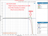
Latest config is almost the same as ASR config, except that the clipping power will be higher, and 2nd harmonic is dominant:
48V supply will get 93dB THD+N at 130W/4R (best THD+N is at 10W)
36V supply will get 93dB THD+N at 75W/4R (best THD+N is at 10W)
So I expect that the frequency response will be almost the same: +0.1dB at 20kHz for 8R load, and -0.1dB at 20kHz for 4R load.
+0.5dB at 40kHz for 8R load and -0.7dB at 40kHz for 4R load.
I sold my Motu M4 and planning to replace it with an ultralite MK5 or upcoming E1DA ADC so I can't do measurements for now.
Attachments
Last edited by a moderator:
Latest config is almost the same as ASR config, except that the clipping power will be higher, and 2nd harmonic is dominant:
48V supply will get 93dB THD+N at 130W/4R (best THD+N is at 10W)
Hi Lester, great work! Just wondering can we use the full 48V of the meanwell supply or would you still suggest trimming it down to 45V?
D
Deleted member 148505
Hi Lester, great work! Just wondering can we use the full 48V of the meanwell supply or would you still suggest trimming it down to 45V?
Hi, if you will use the module in non-PFFB mode, you will get more power if you'll use 48V.
However in PFFB mode, my configuration only gets clean power up to 130W since we've taken away some gain to put into negative feedback. I've tried to lower the negative feedback to get high power output threshold but the midrange sound got thinner, so I made some compromises on the power output.
So 43V to 45V is the best for my current PFFB configuration. You can still use 48V but the output power will still stay the same. (and the heatsink will run hotter as a side effect, output inductors are overkill so they will not overheat)
Regards,
Lester
D
Deleted member 148505
The TPA3255 IC can only handle 2.65Vrms input because the Avdd supply for the analog section only has 7.5V DC pk-pk. So if we increase the negative feedback on PFFB, early clipping occurs because of lower system gain.
We can increase the AVDD supply to higher voltage by adjusting VBG reference voltage. In that case, the input voltage can be increased so there will be no early clipping on PFFB with high NFB.
Though I'm not sure on the impact of increasing AVDD in long term reliability so I stayed with the datasheet's absolute max ratings.
D
Deleted member 148505
Hello
Thank you.
Have you tried poly caps?
Best regards
Roger
Hi Roger,
I didn't understand the question.
Regards,
Lester
I think you are wrong. Max TPA-input level is NOT limiting PFFB. This is a matter of the pre-driver capabilities/OpAmps and their supply voltage.The TPA3255 IC can only handle 2.65Vrms input because the Avdd supply for the analog section only has 7.5V DC pk-pk. So if we increase the negative feedback on PFFB, early clipping occurs because of lower system gain.
We can increase the AVDD supply to higher voltage by adjusting VBG reference voltage. In that case, the input voltage can be increased so there will be no early clipping on PFFB with high NFB.
Though I'm not sure on the impact of increasing AVDD in long term reliability so I stayed with the datasheet's absolute max ratings.
Hi, if you will use the module in non-PFFB mode, you will get more power if you'll use 48V.
Thanks lester!
No worries, it'd be a shame for us to waste all that PFFB optimisation you've done though I imagine just to get a bit of extra output power. What is the loss in output using PFFB do you estimate? I think you may have mentioned this before, I'll go back and have a read again. 👍
D
Deleted member 148505
I think you are wrong. Max TPA-input level is NOT limiting PFFB. This is a matter of the pre-driver capabilities/OpAmps and their supply voltage.
I expected better refute statements other than saying 'you are wrong'. Please enlighten us.
Thanks lester!
No worries, it'd be a shame for us to waste all that PFFB optimisation you've done though I imagine just to get a bit of extra output power. What is the loss in output using PFFB do you estimate? I think you may have mentioned this before, I'll go back and have a read again. ��
Clean power is up to 130W. You can still get the max power although at a higher THD levels. In slaa788a, clean power is up to 160W (at 50V DC rails) so we are losing 30W of clean power.
- Home
- Amplifiers
- Class D
- JLE TPA3255 Build and Modifications