This might (?) be true of some amplifier designs, but it's not true of the ones I'm familiar with - they all share power GND and signal GND. This is certainly the case with TPA325x and TPA311x amplifiers - you will see it in the Texas Instruments datasheets.
I think the subject of grounding is sometimes confused with the subject of earthing. All TPA325x amp boards that I know of have their GND plane exposed around the underside of their mounting holes. These amp boards are intended to be mounted via metal standoffs, making full electrical connection with the base of your metal chassis ... and of course the metal chassis should be earthed. So by design, TPA325x boards are meant to have their power/signal GND earthed. The earth wire from your incoming AC power cable can attach at any point on the chassis, but I prefer to attach this earth wire right up to one of the amp board's metal standoffs.
Now once you have earthed your signal ground at the amplifier in this way - don't earth signal ground on any other device in your signal chain! In an unbalanced signal chain, this is a recipe for ground loops. Or if you insist on doing so, at least earth that device's signal ground via a 100k resistor, which will offer sufficient resistance to any audio signal which might otherwise wish to pass that way.
That's the situation with unbalanced setups.
I going to build an four channel with two 3e TPA3255 and have isolated RCA jacks could I run one ground wire to the amp stand of for all four RCA jacks an only connect signal separate?
Solve, I'm uncertain what you're asking, but let me answer this way: with certain amplifier boards a common convention for GND-to-earth connections is from the RCA connector-to-chassis - either by direct contact between the RCA connector's outer body and the rear panel of the chassis, or sometimes the RCA connector has an insulated mounting, and a wire is run from its outer shell to the floor of the chassis.
But in the case of 3e-audio TPA325x boards this is unnecessary, if these boards are mounted to the metal floor of your chassis with metal standoffs. Just make sure to scrape away the anodising where the standoffs contact the floor. Your RCA connectors can remain insulated against the rear chassis panel.
But in the case of 3e-audio TPA325x boards this is unnecessary, if these boards are mounted to the metal floor of your chassis with metal standoffs. Just make sure to scrape away the anodising where the standoffs contact the floor. Your RCA connectors can remain insulated against the rear chassis panel.
Solve, I'm uncertain what you're asking, but let me answer this way: with certain amplifier boards a common convention for GND-to-earth connections is from the RCA connector-to-chassis - either by direct contact between the RCA connector's outer body and the rear panel of the chassis, or sometimes the RCA connector has an insulated mounting, and a wire is run from its outer shell to the floor of the chassis.
But in the case of 3e-audio TPA325x boards this is unnecessary, if these boards are mounted to the metal floor of your chassis with metal standoffs. Just make sure to scrape away the anodising where the standoffs contact the floor. Your RCA connectors can remain insulated against the rear chassis panel.
Ok thanks.
No problem with two amps sharing same signal earth then and driven with same power supply?
The 2 amp boards sharing the same earth is a good thing, since (I presume) these amps will be fed from a common source device.
Regarding driving the 2 amps from the same power supply, I recall reading about the possibility of beat interference in this scenario, which can be avoided by synchronising the PWM frequency of the 2 amps by configuring one as master, and the other as slave.
But several people here have reported no negative results by sharing a power supply, even without master/slave configuration. You may just need to try it and see.
Yes I read about that master/slave that you move the starting point of one amp and it could distribute the power better.The 2 amp boards sharing the same earth is a good thing, since (I presume) these amps will be fed from a common source device.
Regarding driving the 2 amps from the same power supply, I recall reading about the possibility of beat interference in this scenario, which can be avoided by synchronising the PWM frequency of the 2 amps by configuring one as master, and the other as slave.
But several people here have reported no negative results by sharing a power supply, even without master/slave configuration. You may just need to try it and see.
I try regular first if it works.
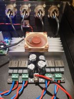
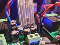
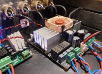
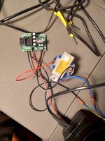
The heatsink gets quite hot on this board so I wanted to do something about it. The temperature is probably within spec but it unnerves me especially as it will be tucked in to a rack cabinet.
This isn't the first time I have used a Noctua NF-A4x10 40mm fan, they're pretty good and they are the quietest fans I have used. Using an LM2596 board I have taken the 30v down to a voltage/slow enough speed to balance air movement and SPL. It runs quite quiet like this and the heatsink is super cool even with a very low air flow.
The question is, how to mount? I think I might drill holes in to the sides of the heatsink fins on both sides and just cable tie it in place through he fan mounting holes. It isn't an elegant solution but it will work.
---------------------------------------------
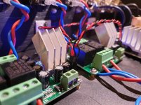
Again, I am concerned about the heat dissipation of the speaker protection boards as these get very hot. I switched them over for the slightly bigger sinks with at least 200% more surface area/fin. The are cooler but there is some of the transistor heat die showing. Does anyone think this will be a problem? At least 2/3 is in contact with the heat sink as shown in the second pic.
This isn't the first time I have used a Noctua NF-A4x10 40mm fan, they're pretty good and they are the quietest fans I have used. Using an LM2596 board I have taken the 30v down to a voltage/slow enough speed to balance air movement and SPL. It runs quite quiet like this and the heatsink is super cool even with a very low air flow.
The question is, how to mount? I think I might drill holes in to the sides of the heatsink fins on both sides and just cable tie it in place through he fan mounting holes. It isn't an elegant solution but it will work.
---------------------------------------------
Again, I am concerned about the heat dissipation of the speaker protection boards as these get very hot. I switched them over for the slightly bigger sinks with at least 200% more surface area/fin. The are cooler but there is some of the transistor heat die showing. Does anyone think this will be a problem? At least 2/3 is in contact with the heat sink as shown in the second pic.
Attachments
All done!
I took a heatsink from a knackered TDA7492 board, shaped it and cut it in half and attached to the protection boards. Huge increase in mass and surface area but they still get very warm. However, if these get warm then the initial ones must have been woefully under spec'd.
Fan attached to the amp board heatsink as mentioned and as expected, not elegant but perfectly sound.
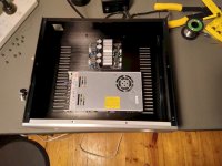
Tested overnight and didn't explode or warp me to a different level so I think it's time to install it!
I took a heatsink from a knackered TDA7492 board, shaped it and cut it in half and attached to the protection boards. Huge increase in mass and surface area but they still get very warm. However, if these get warm then the initial ones must have been woefully under spec'd.
Fan attached to the amp board heatsink as mentioned and as expected, not elegant but perfectly sound.
Tested overnight and didn't explode or warp me to a different level so I think it's time to install it!
Attachments
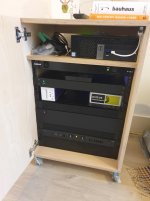
Morning STUNT!
I got it installed last night and gave it a good listening to.
System comprised of:
Computer -> Xonar U5 -> SPDIF -> MiniDSP 10x10 -> TPA3251 & STA-400D (Hypex UCD for subs) -> 3-way speakers.
It sounds good but, before I go on, I am not one for What Hifi? speak. The amp is dead quiet but it certainly shows the MiniDSP up for being quite noisey - somethig I'd forgotten as the amps it replaces are Parasound Zamps which have input gain adjustment. I will need to up my L-Pad for the compression driver for sure.
It sounds as good or better than what it replaced. I don't notice anything particularly different. At least nothing I can quanitify without saying something like "It's stereo envelope cleaved the room with an engaging tone that pulled me from my seat and gave neither an analytical nor complimentary listening experience. It certainly does not make Diana Krall sound good - but what speaker can?"
It sounds good.
My next step is to replace:
- Power filter caps with Nichicon UKT 1000uf & 2200uf
- Audio coupling caps with Nichicon UFG 10uf caps (I want to use Wima MKP4 caps but they don't come small enough to fit on the board)
- Output filter caps to EPCOS B32529
I don't expect this to change a lot but the onboard components are ChengX etc. and I think it would be for the best in any event.
As for the PFFB - I spoke to Jason at 3E and he said it is not recommended on this board. It's a shame but fair does. I am not exactly sure why - perhaps the components on this board are not inline with the TI applicatyion note that is available.
(Anyway later this year I plan to up my game to some sort of LLC PSU and TPA3255 with PFFB setup)
Would people recommend a CLC filter between the PSU and board. I have been looking for a guide but I am a bit confused by them!
Attachments
Nice, I feel that’s certainly good praise.
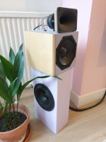
I like your speakers, I assume there is thread relating to them? I’ll have a search on DIYA anyway. Also, I’ll be keen to see the mods you do the board, hopefully you will update this thread.
I’m likely to do the PFFB mod to my amps once I get a DAC with balanced out. On that topic why do you need to have a balanced source when doing the PFFB mod?
BTL vs SE for the TPA3251?
You are providing both inspiration and motiviation.
As I understand it you are using a TPA3251 amp to drive 4 independent audio outputs Doesn't this mean you are running the TPA3251 outputs in single-ended mode?
The TPA3251 does have inbuilt protection for over-current, DC speaker protection and other faults. What motivated you to include speaker protection boards in your build. Is there something lacking with the TPA3251 in-built fault protection or are you just adding extra protection insurance?
You mention you have modified the speaker protection boards so they will work with a BTL amplifer output. Is this really necessary (I'm a bit slow)?
How can the modified protection board provide any protection against a DC offset in the amplifier output? It would have to measure current and this would require at least a 0.5-1.0 W resistor on the speaker protection board. I don't see any large resistors on the protection board.
I'm building up a system using the 3e TP3255 board with a Meanwell supply. It will be stereo and the amp will operate in BTL mode. Additional speaker protection is something I'm currently considering. Not as simple as I first thought. I hope my system will sound as good as yours.
Regards ...
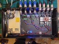
I fancied trying Class-D for my main system so last year I bought a 3E TPA3251 4x100w board and I have finally got the time and parts to do it. I also wanted to make this chassis futureproof so I can swap in other amp/PSU combos in the future, always keeping input balanced.
You are providing both inspiration and motiviation.
As I understand it you are using a TPA3251 amp to drive 4 independent audio outputs Doesn't this mean you are running the TPA3251 outputs in single-ended mode?
The TPA3251 does have inbuilt protection for over-current, DC speaker protection and other faults. What motivated you to include speaker protection boards in your build. Is there something lacking with the TPA3251 in-built fault protection or are you just adding extra protection insurance?
You mention you have modified the speaker protection boards so they will work with a BTL amplifer output. Is this really necessary (I'm a bit slow)?
How can the modified protection board provide any protection against a DC offset in the amplifier output? It would have to measure current and this would require at least a 0.5-1.0 W resistor on the speaker protection board. I don't see any large resistors on the protection board.
I'm building up a system using the 3e TP3255 board with a Meanwell supply. It will be stereo and the amp will operate in BTL mode. Additional speaker protection is something I'm currently considering. Not as simple as I first thought. I hope my system will sound as good as yours.
Regards ...
Thanks for the link to the thread!
I’m in Deptford, are you a Southie?
Barking now, though, I've lived everywhere but west and north west London!
You are providing both inspiration and motiviation.
As I understand it you are using a TPA3251 amp to drive 4 independent audio outputs Doesn't this mean you are running the TPA3251 outputs in single-ended mode?
The TPA3251 does have inbuilt protection for over-current, DC speaker protection and other faults. What motivated you to include speaker protection boards in your build. Is there something lacking with the TPA3251 in-built fault protection or are you just adding extra protection insurance?
You mention you have modified the speaker protection boards so they will work with a BTL amplifer output. Is this really necessary (I'm a bit slow)?
How can the modified protection board provide any protection against a DC offset in the amplifier output? It would have to measure current and this would require at least a 0.5-1.0 W resistor on the speaker protection board. I don't see any large resistors on the protection board.
I'm building up a system using the 3e TP3255 board with a Meanwell supply. It will be stereo and the amp will operate in BTL mode. Additional speaker protection is something I'm currently considering. Not as simple as I first thought. I hope my system will sound as good as yours.
Regards ...
I'll have to pass on most of this as I don't know the answer. But simply put there is more than the chip in the chain to go wrong. Components on the board, the PSU and the little on/off click I get on power cycle. Yes it has DC protection but from my understanding this is more for short circuit or a stray power supply cable, perhaps. It doesn't hurt to have extra, eh?
I use compression drivers and a PA woofer so I can definitely hear on/off noises but not as loud as the relays!
I merely followed the instructions that the seller page has for the board. Removing two resistors and connecting the hot side of the speaker cable along with a ground from the amp. The ground reference I used is not connected to the speaker inputs as I am using the amplifier auxillary 12v supply to power the boards so comes in via the DC input. (something I need to remember going forward when I change the set up in the chassis)
This amplifier board has two TPA3251 chips on it ergo the fan added to the heatsink. TBH I think the sink is a little small for the peak power the board can generate. 3E specify an optimal voltage of 30v due to high heat dissipation above this figure so it makes sense to have extra cooling in my view. It's a very quiet fan.
I ran the amp board comfortably on 36v until a realised that my LM2596 board has a max input of 35v and shut off the fan. So I thought I'd sort out a seperate DC supply for the fan and protection boards when I do my next chassis reshuffle.
I am thinking about upgrading to a Connexelectronic LLC PSU which has it's own aux power supply so I could potentially run the fan and protection boards from this. However brexit has put the kibosh on this for the time being.
Please share your projects!
Speaker Protection
Thanks for your response. The key point is that your board has two amplifier chips. Hopefully the TPA3255 2 channel board runs much cooler.
The protection board is very cheap. I will order one, configure it for BTL and carry out some tests to see how well the DC protection works. I want to power the protection board from a 240/9 VAC transformer. These cost less than $10.
Last edited:
The protection board is very cheap. I will order one, configure it for BTL and carry out some tests to see how well the DC protection works. I want to power the protection board from a 240/9 VAC transformer. These cost less than $10.
How did you get on?
Some Progress
Hi,
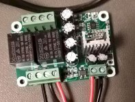
I purchased two of the Speaker protection modules to see how they would perform with R6 and R8 removed.
A protection board was powered up using a transformer with 8.2 VAC output. When the board is first powered up the blue led flashes for a few seconds and then becomes continuously on. At the same time a relay thunk is heard. This is the startup delay.
If a DC voltage of +5 VDC is applied across Audio Input R and GND the blue LED starts flashing again and a relay thunk is heard as the contacts change state. This is normal operation with a single ended AMP.
After R6 and R8 are removed the board still provides the start up delay. But, it no longer detects a DC voltage on the L or R inputs. So I don't think it is going to provide protection against DC. It will have to measuring the DC voltage across the speaker in order to work. Just as well they only cost a few dollars. I will use them on another project.
More to follow ....
Hi,
I purchased two of the Speaker protection modules to see how they would perform with R6 and R8 removed.
A protection board was powered up using a transformer with 8.2 VAC output. When the board is first powered up the blue led flashes for a few seconds and then becomes continuously on. At the same time a relay thunk is heard. This is the startup delay.
If a DC voltage of +5 VDC is applied across Audio Input R and GND the blue LED starts flashing again and a relay thunk is heard as the contacts change state. This is normal operation with a single ended AMP.
After R6 and R8 are removed the board still provides the start up delay. But, it no longer detects a DC voltage on the L or R inputs. So I don't think it is going to provide protection against DC. It will have to measuring the DC voltage across the speaker in order to work. Just as well they only cost a few dollars. I will use them on another project.
More to follow ....
Attachments
And some more
Hi,
The amplifier will provide two audio channels. The power output is expected to be around 80-90 watts RMS per channel when driving an eight ohm load. The amplifier module is EAUMT-0260-20B and was purchased on AliExpress. It only includes a single TPA3255, so it should run cooler than the 4 channel board.
The amplifier module will be powered by a MeanWell LRS-350-36 SMPS. This power supply was purchased from a local distributer in Melbourne and only cost $58 AUD. This is much cheaper than building up a linear power supply.
An aluminium enclosure measuring about 35cm W x 30cm D x 8 cm H was purchased on AliExpress. The price of the enclosure was about $40 AUD, but the freight cost was bad.
Currently planning the layout and ordering bits from Mouser. Will then drill the enclosure and start mounting components.
Speaker refoam this weekend.
Attachments
- Home
- Amplifiers
- Class D
- 3E TPA3251 / LRS-350-36 / Hifi2000 Build