I'm starting a new monoblock amplifier build using the Purifi 1et400a module and thought it might be interesting for others to follow along and lend their input. This will be my third pair of monoblock amps built this year, after a pair of F5 Turbo v2 amps and a pair of Neurochrome Mod-286s.
My last exposure to class D was with a pair of Nord Hypex NC500 amps using the Hypex SMPS1200 supply and Nord's rev D input buffers. These amps were quiet, clean, detailed and powerful, but I also thought they sounded kind of flat - I never really had the emotional connection with the music that I do with other amps.
Virtually everything has changed in my system since then, and I've gotten much more into DIY, so I thought I'd give class D another try. But I don't want to just throw a couple of pre-built modules into a box and call it good. So my amps will be a bit different than the norm.
First, I am building these with a big linear power supply. This is partially because I can at least build this myself, but also to see if it has any affect on the way the amp sounds.
I'm also designing the enclosure so that I have room to experiment with different input buffers. I'm going to start with the Neurochrome board to get the amp operational quickly and to have a baseline, but then I plan to build several more designs using custom PCBs. I have enough room for buffer PCBs that are 130mm x 85mm which should allow for a lot of options.
The design approaches I am considering include:
I'm hoping to do a new input buffer every month or two (the first one will take a while since I'm learning KiCad). This will keep me busy for a while. I'm not sure I'll do all of these, depending on how it goes. If you've got thoughts on what you think might be the most interesting, please chime in.
I've sent the enclosure drawings to Modushop (Slimline 3U/350mm), so hopefully I'll have the enclosures in a few weeks.
I'll make follow-on posts with additional details.
My last exposure to class D was with a pair of Nord Hypex NC500 amps using the Hypex SMPS1200 supply and Nord's rev D input buffers. These amps were quiet, clean, detailed and powerful, but I also thought they sounded kind of flat - I never really had the emotional connection with the music that I do with other amps.
Virtually everything has changed in my system since then, and I've gotten much more into DIY, so I thought I'd give class D another try. But I don't want to just throw a couple of pre-built modules into a box and call it good. So my amps will be a bit different than the norm.
First, I am building these with a big linear power supply. This is partially because I can at least build this myself, but also to see if it has any affect on the way the amp sounds.
I'm also designing the enclosure so that I have room to experiment with different input buffers. I'm going to start with the Neurochrome board to get the amp operational quickly and to have a baseline, but then I plan to build several more designs using custom PCBs. I have enough room for buffer PCBs that are 130mm x 85mm which should allow for a lot of options.
The design approaches I am considering include:
- Simple discrete op-amp design using one Weiss OP2-BP for each balanced leg. This is similar in concept to many of the commercial Hypex and Purifi amps.
- Fully balanced design with quality op-amp (such as OPA627) feeding a single-ended class A mosfet buffer for each leg (similar to Whammy design).
- Fully discrete line stage with JFET input and MOSFET output stage for each leg (similar to Salas DCG3).
- Similar to above with bipolar outputs.
- Tube-based design (see this thread - https://www.diyaudio.com/forums/tubes-valves/361030-help-tube-buffer.html).
I'm hoping to do a new input buffer every month or two (the first one will take a while since I'm learning KiCad). This will keep me busy for a while. I'm not sure I'll do all of these, depending on how it goes. If you've got thoughts on what you think might be the most interesting, please chime in.
I've sent the enclosure drawings to Modushop (Slimline 3U/350mm), so hopefully I'll have the enclosures in a few weeks.
I'll make follow-on posts with additional details.
I would contribute toward costs for someone to evaluate / ideally create a DIY cookbook / design using this BTSB buffer, so that either true balanced differential or SE inputs could be used as desired.
Best Thing since Sliced Bread Buffer
BTSB Buffer - SE/Bal to SE/Bal Buffer GB
or balanced / differential on the power amp, with BTSB coupled with a clean SPL gain control pre-amp?
Best Thing since Sliced Bread Buffer
BTSB Buffer - SE/Bal to SE/Bal Buffer GB
or balanced / differential on the power amp, with BTSB coupled with a clean SPL gain control pre-amp?
Input buffer and Case Design
The Neurochrome buffer I am using as a starting point is pretty similar to the BTSB buffer, using a dual op amp to provide a differential input that can also handle single-ended inputs, and the same LME49724 as the final driver.
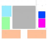
I've attached some pdf files of the drawings for the front panel and back panel. The bottom panel drawing was too big, so I attached a jpg showing the layout. This is a view from the top with the front toward the bottom. The two orange rectangles are the main positive and negative PS boards, the green rectangle is the op-amp supply (unregulated +/- about 18v), the light blue rectangle is the gate drive supply (regulated 15V referenced to the main negative supply).
The large gray rectangle in the middle is the mounting plate for a Toroidy 1500VA Supreme Audio custom transformer, with secondaries for all the required voltages.
The magenta rectangle is the Purifi module, and the dark blue rectangle is for the Neurochrome buffer. There are mounting holes for a larger 130mm x 85mm buffer board.
The enclosure includes internal panels separating the buffer and Purifi module from the rest of the board.
I am also planning to have a small 12V power supply mounted on the back panel that will drive an audio sense circuit for automatic turn on (also mounted on the back panel). There is also a soft start PCB mounted on the back panel that includes a low voltage power switch mounted on the front panel.
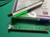
The front panel also includes a window to show a 32-segment LED power meter. Separate switches on the back panel are used to turn on and off the power meter and the auto turn on circuit.
I prefer monoblock amps because of my system layout. I don't want anything sitting between the speakers and it's a lot easier to route a balanced interconnect than big speaker cables.
I haven't added up the total cost, but this is obviously not a cost-conscious build. With all the machining, custom printing, etc. on the case, the cases alone were over $1000. I'd estimate that I'll be into these for a bit less than $3000 when I'm done (with the initial Neurochrome buffer).
The Neurochrome buffer I am using as a starting point is pretty similar to the BTSB buffer, using a dual op amp to provide a differential input that can also handle single-ended inputs, and the same LME49724 as the final driver.
I've attached some pdf files of the drawings for the front panel and back panel. The bottom panel drawing was too big, so I attached a jpg showing the layout. This is a view from the top with the front toward the bottom. The two orange rectangles are the main positive and negative PS boards, the green rectangle is the op-amp supply (unregulated +/- about 18v), the light blue rectangle is the gate drive supply (regulated 15V referenced to the main negative supply).
The large gray rectangle in the middle is the mounting plate for a Toroidy 1500VA Supreme Audio custom transformer, with secondaries for all the required voltages.
The magenta rectangle is the Purifi module, and the dark blue rectangle is for the Neurochrome buffer. There are mounting holes for a larger 130mm x 85mm buffer board.
The enclosure includes internal panels separating the buffer and Purifi module from the rest of the board.
I am also planning to have a small 12V power supply mounted on the back panel that will drive an audio sense circuit for automatic turn on (also mounted on the back panel). There is also a soft start PCB mounted on the back panel that includes a low voltage power switch mounted on the front panel.
The front panel also includes a window to show a 32-segment LED power meter. Separate switches on the back panel are used to turn on and off the power meter and the auto turn on circuit.
I prefer monoblock amps because of my system layout. I don't want anything sitting between the speakers and it's a lot easier to route a balanced interconnect than big speaker cables.
I haven't added up the total cost, but this is obviously not a cost-conscious build. With all the machining, custom printing, etc. on the case, the cases alone were over $1000. I'd estimate that I'll be into these for a bit less than $3000 when I'm done (with the initial Neurochrome buffer).
Attachments
 Linear supply.
Quasimodo Snubber Test
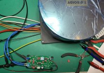
I built one of Mark Johnson's Quasimodo transformer snubber testers (thanks Mark) to determine the values to use for the snubbers. My Toroidy transformers have the following secondaries based on 115V input:
2 x 45V @ 15.6A
3 x 15V @ 2A
The optimal snubber values for the 45V primaries are:
Cx 10nF
Cs 150nF
Rs 8.2ohm
For the 15V secondaries:
Cx 10nF
Cs 150nF
Rs 9.1ohm
I have to order the correct value resistors before I can finish up the power supplies.
Attachments
I built one of Mark Johnson's Quasimodo transformer snubber testers (thanks Mark) to determine the values to use for the snubbers. My Toroidy transformers have the following secondaries based on 115V input:
2 x 45V @ 15.6A
3 x 15V @ 2A
The optimal snubber values for the 45V primaries are:
Cx 10nF
Cs 150nF
Rs 8.2ohm
For the 15V secondaries:
Cx 10nF
Cs 150nF
Rs 9.1ohm
I have to order the correct value resistors before I can finish up the power supplies.
Be careful with supply pumping. You can easily get an increase of voltage out of the transformer. 45*sqrt(2) will give you 63.6V and if you need to pull a lot of power depending on your speakers, you may easily get to 70V or more and trip the over voltage protection of the Purifi module.
Also any local utility AC variations may make this even more critical.
The solution for monoblocks is to use MOSFETS and not diodes for rectification. Then the power supply will not suffer from pumping. This applies to both switching and linear supplies.
This is a good point, but I'm not too worried with my speakers and PS implementation. My current speakers are 93db/w and a fairly easy 8ohm load. The new speakers I'm building are 98db/w efficiency (also a fairly easy load) and are line sources, so sound output doesn't drop as fast as point sources. In both these cases, the amp will only drive the speakers about about 80Hz (fed through a cap to roll off the lowest frequencies), so it will mostly be coasting along driving my speakers.
Also, my power supply is a CRCRC design, so there will be several volts dropped across the resistors under higher current. So I don't expect the voltage will get close to hitting the max on the Purifi modules from charge pumping. But I will try to do some testing to test this.
Also, my power supply is a CRCRC design, so there will be several volts dropped across the resistors under higher current. So I don't expect the voltage will get close to hitting the max on the Purifi modules from charge pumping. But I will try to do some testing to test this.
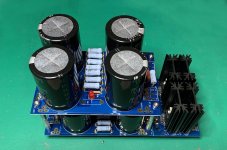
I'm using the DIYAudio Store Universal Power Supply boards for the main power supply. I've split the positive and negative supplies so they will mount across the front of the amp, shown in orange in post #4. I actually have two boards, one mounted about the other, so that I can use eight main filter caps per rail, and set up a CRCRC supply.
I just got the shipping notice from Modushop so I should have the chassis sometime next week.
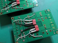
The photo shows just the positive rail for one monoblock.
I just got the shipping notice from Modushop so I should have the chassis sometime next week.
The photo shows just the positive rail for one monoblock.
Attachments
Buffer/Op Amp power supply
The Purifi module requires a +/- 12v Op-Amp supply (~27ma). In addition, the buffer board needs a low voltage supply. The Neurochrome board that I am starting with has the ability to plug in regulator boards to generate these voltages from an unregulated input connection, and will also use the regulated outputs for it's own buffer circuitry.
My future plans include buffer boards that will require higher current draw and will be able to operate at somewhat higher voltage +/- 15v or so. So I decided to implement a higher current unregulated linear supply which can be regulated on the buffer.
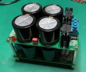
I found some bare PCBs from jimsaudio.com which were the right size and provided adequate functionality. I'm using two of these boards for each monoblock. The boards are designed to provide a +/- supply, but I decided to implement a CRC supply by daisy-chaining two boards with resistors between them. Each board has 13600uF for each rail, and I'm using two 3ohm resistors in parallel between the banks.
These boards did not have the transformer snubber connections I wanted, so I added the caps to the underside of the board connected to the transformer.
The Purifi module requires a +/- 12v Op-Amp supply (~27ma). In addition, the buffer board needs a low voltage supply. The Neurochrome board that I am starting with has the ability to plug in regulator boards to generate these voltages from an unregulated input connection, and will also use the regulated outputs for it's own buffer circuitry.
My future plans include buffer boards that will require higher current draw and will be able to operate at somewhat higher voltage +/- 15v or so. So I decided to implement a higher current unregulated linear supply which can be regulated on the buffer.
I found some bare PCBs from jimsaudio.com which were the right size and provided adequate functionality. I'm using two of these boards for each monoblock. The boards are designed to provide a +/- supply, but I decided to implement a CRC supply by daisy-chaining two boards with resistors between them. Each board has 13600uF for each rail, and I'm using two 3ohm resistors in parallel between the banks.
These boards did not have the transformer snubber connections I wanted, so I added the caps to the underside of the board connected to the transformer.
Attachments
Last edited:
Progress on first monoblock
I haven't had a lot of time to work on the amps over the last couple of weeks, but I managed to get one of the power supplies installed in the chassis today and got everything checked out.
After doing some testing on the main power supplies, I found that my output voltage is a bit on the high side with my home mains voltage. I'm measuring 69V on the power supplies with no load. These transformers are huge, so they aren't going to sag much once I've got the amp modules hooked up, particularly since idle current is so low. So I decided to increase the first-stage resistors in my CRCRC supply up to about 0.2 ohm. It was closer to 0.05 ohms. I'm hoping that this will add a bit more drop under high current and reduce the chances that I'll trigger the over-voltage protection on the Purifi modules. Worst case, I'll have to swap out the transformers.
My speakers are pretty efficient (current speakers are 92.5db/w and the speakers I am planning to build over the next several months are 98db/w, so I don't expect to be pushing the Purifi modules too hard.
The main supply has 134KuF for each monoblock, with an additional 54K for the low voltage supply. I'm using an AMB omega-11 regulated supply to generate the 15V gate drive. And I've got a 12V supply mounted to the back panel to drive accessories - the LED on the power button and an LED power meter which will mount in the front panel. Each of these has it's own switch to disable when I want the amp to be dark.
I'm using a Hypex soft-start module to control power. This provides a low-voltage power switch option as well as the soft start.
I decided to eliminate the audio-level-sense power-on feature, partly because it wasn't compatible with the Hypex module without making some changes and I decided I probably wouldn't use it much anyway.
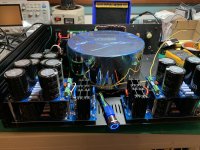
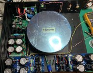
Photos show the LED power meter I'm using and the progress on the first of the two monoblocks. I have all the PCBs assembled and the backpanel wired for the second amp as well, but not installed in the chassis.
I haven't had a lot of time to work on the amps over the last couple of weeks, but I managed to get one of the power supplies installed in the chassis today and got everything checked out.
After doing some testing on the main power supplies, I found that my output voltage is a bit on the high side with my home mains voltage. I'm measuring 69V on the power supplies with no load. These transformers are huge, so they aren't going to sag much once I've got the amp modules hooked up, particularly since idle current is so low. So I decided to increase the first-stage resistors in my CRCRC supply up to about 0.2 ohm. It was closer to 0.05 ohms. I'm hoping that this will add a bit more drop under high current and reduce the chances that I'll trigger the over-voltage protection on the Purifi modules. Worst case, I'll have to swap out the transformers.
My speakers are pretty efficient (current speakers are 92.5db/w and the speakers I am planning to build over the next several months are 98db/w, so I don't expect to be pushing the Purifi modules too hard.
The main supply has 134KuF for each monoblock, with an additional 54K for the low voltage supply. I'm using an AMB omega-11 regulated supply to generate the 15V gate drive. And I've got a 12V supply mounted to the back panel to drive accessories - the LED on the power button and an LED power meter which will mount in the front panel. Each of these has it's own switch to disable when I want the amp to be dark.
I'm using a Hypex soft-start module to control power. This provides a low-voltage power switch option as well as the soft start.
I decided to eliminate the audio-level-sense power-on feature, partly because it wasn't compatible with the Hypex module without making some changes and I decided I probably wouldn't use it much anyway.
Photos show the LED power meter I'm using and the progress on the first of the two monoblocks. I have all the PCBs assembled and the backpanel wired for the second amp as well, but not installed in the chassis.
Attachments
First channel is running
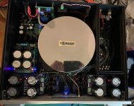
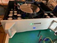
One channel complete (almost). I still need to get a laser cut acrylic panel for the front panel in front of the LED power display. But otherwise everything seems to be working. It's only been powered on for an hour, so it still has some a lot of burn-in left. I'm just playing it through a cheap speaker, so can't comment on how it sounds. I'm going to wait until I have the second channel finished before I try it on better speakers.
Please excuse my messy work area. I don't really have enough space to work right now. I've got a new electronics workbench on order which will have a shelf above the desk to move some of the test equipment up.
Attachments

Purifi monoblocks - SQ comparisons
I've been running these amps for about 6 weeks now using the Neurochrome buffers. I'm quite pleased with the sound. A week or so ago, I spent a few hours comparing these my Parasound JC5 and a pair of Neurochrome Mod-286 monoblocks I built.
I liked the Purifi amps and JC5 better than the Mod-286 amps, although the Mod-286 acquits itself quite well, particularly for the build cost. The Purifi amps and JC5 both had strengths and weaknesses, but I'd be happy with either from a sound quality perspective. But the reduced heat and improved efficiency tips the scale in favor of the Purifi amps.
The Purifis have a wider sound stage and a bit more slam and weight to the mid-bass. The JC5 was a bit smoother in the upper frequencies. But the differences are pretty subtle.
I decided to try a pair of buffers from VTV, discussed in the next post.
VTV Tube Input Buffer for Purifi
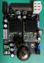
VTV Amplifier makes a couple of different input boards that will work with the Hypex NC500 and Purifi class D modules. I purchased a pair of their tube input buffers which are their more expensive option.
These use a 6922 triode tube differential input driving a pair of Weiss discrete op amps. The board was designed by Sparkos Labs and includes a pair of Sparkos discrete regulators for the op-amp supply.
These boards use different connectors (except for the main 6-pin power connector), so I had to rewire the low voltage power supply, input and output connections. If you are using the Hypex switch mode power supplies, they are easy to hook up since they use matching connectors.
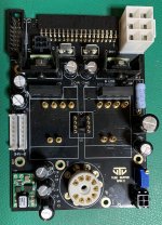
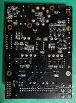
I've included photos of the PCBs without the tube or opamps installed, both top and bottom.
If you decide to give these a try, here are a couple notes that might help.
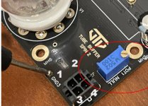
The input signals plug into a 4-pin molex connector near the tube. I've included a photo showing the pin numbering. Pin 1- non-inverting analog in. Pin 2 - inverting analog in. Pin 3 - not connected. Pin 4 - Gnd.
The 14 pin J1 connector is used for the Vaux inputs. These feed the Sparkos regulators, so the input voltage should be in the +/- 20-22V range. The only pins that need to be used are Pin1 - Vaux+, Pin2 - Vaux-, Pin3 Gnd, and Pin6 nAmpOn.
The 7 pin J7 connector is used as a second connection to Vaux (just the positive) rail to provide power for the tube heater. The board includes a DC-to-DC converter that converts this voltage to the 6.3V filament voltage. Only two pins on this connector are connected. Pin 3 - Vaux+ and Pin 5 - Gnd. VTV provides a cable with connectors on both ends to connect between the buffer and J5 on the Hypex SMPS.
The nAmpOn signal must be driven to ground in order to enable the Purifi module. If you are using the Hypex SMPS, connected using the standard 14 conductor ribbon cable, this will be handled automatically. But the buffer board also includes its own mute circuit to keep the Purifi module inputs clamped for 45 seconds to give the tube circuit time to reach operating temperature.
I've got one of my two monoblocks updated with the new board and hope to have the other done by this weekend.
VTV Amplifier makes a couple of different input boards that will work with the Hypex NC500 and Purifi class D modules. I purchased a pair of their tube input buffers which are their more expensive option.
These use a 6922 triode tube differential input driving a pair of Weiss discrete op amps. The board was designed by Sparkos Labs and includes a pair of Sparkos discrete regulators for the op-amp supply.
These boards use different connectors (except for the main 6-pin power connector), so I had to rewire the low voltage power supply, input and output connections. If you are using the Hypex switch mode power supplies, they are easy to hook up since they use matching connectors.
I've included photos of the PCBs without the tube or opamps installed, both top and bottom.
If you decide to give these a try, here are a couple notes that might help.
The input signals plug into a 4-pin molex connector near the tube. I've included a photo showing the pin numbering. Pin 1- non-inverting analog in. Pin 2 - inverting analog in. Pin 3 - not connected. Pin 4 - Gnd.
The 14 pin J1 connector is used for the Vaux inputs. These feed the Sparkos regulators, so the input voltage should be in the +/- 20-22V range. The only pins that need to be used are Pin1 - Vaux+, Pin2 - Vaux-, Pin3 Gnd, and Pin6 nAmpOn.
The 7 pin J7 connector is used as a second connection to Vaux (just the positive) rail to provide power for the tube heater. The board includes a DC-to-DC converter that converts this voltage to the 6.3V filament voltage. Only two pins on this connector are connected. Pin 3 - Vaux+ and Pin 5 - Gnd. VTV provides a cable with connectors on both ends to connect between the buffer and J5 on the Hypex SMPS.
The nAmpOn signal must be driven to ground in order to enable the Purifi module. If you are using the Hypex SMPS, connected using the standard 14 conductor ribbon cable, this will be handled automatically. But the buffer board also includes its own mute circuit to keep the Purifi module inputs clamped for 45 seconds to give the tube circuit time to reach operating temperature.
I've got one of my two monoblocks updated with the new board and hope to have the other done by this weekend.
Attachments
IMO crazy pricey for input buffering, and I don't want tubes
have you looked at the BTSB project? BTSB Buffer - SE/Bal to SE/Bal Buffer GB
I would really like to know how much IRL added value the VTV boards offer
Edit: apologies for the repetition, OP feel free to just ignore, I realize not everyone is struggling financially
have you looked at the BTSB project? BTSB Buffer - SE/Bal to SE/Bal Buffer GB
I would really like to know how much IRL added value the VTV boards offer
Edit: apologies for the repetition, OP feel free to just ignore, I realize not everyone is struggling financially
Last edited:
@john61ct - Yes, I agree it is expensive relative to other Purifi/Hypex buffer boards, but it's also quite a bit more sophisticated. Whether the SQ justifies the price is an individual decision (one that I haven't made for myself yet).
I realize that many people on this forum that build DIY are on limited budgets and are doing so to save money (a great reason to get into DIY). I'm fortunate to be at a stage in my life where I am reasonably well off and build DIY because I enjoy it and I can build components the way I want that would not necessarily be commercially viable.
It's possible to build an excellent amplifier using the Purifi modules, Hypex SMPS and one of several much-lower-priced input buffers. The Neurochrome buffer that I have been using is an example of a very good sounding buffer that is significantly less expensive.
I have looked at the BTSB buffer but have not built one. It is quite similar to the AMB Labs A24 buffer that I am using in my preamp. Different choices for TI op-amps, but similar topology and performance. The problem with the BTSB (and the AMB A24 for this application) is that it is not designed to interface directly to the Purifi module, so you'll still need another board for the proper connections.
The Neurochrome buffer board is also similar, although again uses different opamps (fairly similar performance) but is designed specifically for the Purifi and Hypex NC500. This board is fully assembled using SMT parts, and is very well engineered.
From a strict measured performance perspective, I suspect it will be hard to beat the performance of a buffer like the Neurochrome. But I'm not in this hobby to look at numbers and have found I often prefer the sound of products that don't necessarily have the best measured specs. After I've had a chance to listen to the VTV buffers for a while, I'll report back with my impressions.
@daniboun - That looks like a nice simple design. Congrats! That should provide an excellent option for DIYers looking to build a Purifi amp with the best price/performance.
- Status
- This old topic is closed. If you want to reopen this topic, contact a moderator using the "Report Post" button.
- Home
- Amplifiers
- Class D
- Purifi Monoblocks