Hi!
I had been looking for a new amplifier for my small home office for a little while.
My requirements are:
- Has 1U 19" rackmount enclosure, so it can sit neatly in my audio rack
- Takes in balanced +4dBu "Pro" Line Level (so I can make the most of my Glensound AOIP44 DAC)
- Has a low idle power / is energy efficient
- Isn't a humongous PA amplifier for use in a venue
- Doesn't sound too bad (I don't have great ears, so not sure I can really tell subtle improvements in audio quality)
Most 19" rack-mount amps are designed for big rooms, rather than local monitoring. But I did find this:
CANFORD UTILITY POWER AMPLIFIER Mk.2 2x 45W/8, balanced inputs, rackmount, 1U
And there are some older models regularly available on eBay but judging by the size of the heatsinks, I imagine it isn't very energy efficient.
Besides, I thought it might be fun to build something myself - so here I am and looking at building a Class D amplifier in a 1U case!
I did buy the TPA3255 based board from 3e Audio and have it connected up using my bench power supply and it sounds pretty good! But I think I am going to sell it on because it is so massively overkill for my small room. And it is higher than 1U (40mm), so I would have to replace the big capacitors and heatsink - all a bit too risky for what is currently a nice, fully functional board!
My part list is currently looking like this:
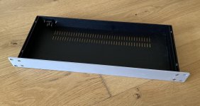
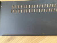
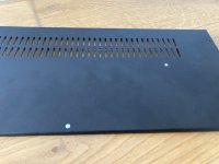
- A Slim Line 1U case from Modushop
- A Mean Well 24V / 100W Embedded Switch Mode Power Supply
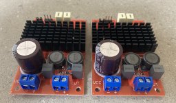
- A pair of super-cheap mono TPA3116 red boards from eBay, which take a balanced input
- Neutrik XLR sockets
- ...
The cheapness of the TPA3116 boards alarms me , but to my ears, they sound pretty good. They do have a little bit of hiss when the volume is turned right up. I might replace with a TPA3250 based board in the future, if I can find or maybe make something.
And I might add a volume control / attenuator in the future but for now, I am very happy with a Monicon Passive Monitor Controller, which sits on my desk.
So providing it all works, it shouldn't be a very complex build...
I had been looking for a new amplifier for my small home office for a little while.
My requirements are:
- Has 1U 19" rackmount enclosure, so it can sit neatly in my audio rack
- Takes in balanced +4dBu "Pro" Line Level (so I can make the most of my Glensound AOIP44 DAC)
- Has a low idle power / is energy efficient
- Isn't a humongous PA amplifier for use in a venue
- Doesn't sound too bad (I don't have great ears, so not sure I can really tell subtle improvements in audio quality)
Most 19" rack-mount amps are designed for big rooms, rather than local monitoring. But I did find this:
CANFORD UTILITY POWER AMPLIFIER Mk.2 2x 45W/8, balanced inputs, rackmount, 1U
And there are some older models regularly available on eBay but judging by the size of the heatsinks, I imagine it isn't very energy efficient.
Besides, I thought it might be fun to build something myself - so here I am and looking at building a Class D amplifier in a 1U case!
I did buy the TPA3255 based board from 3e Audio and have it connected up using my bench power supply and it sounds pretty good! But I think I am going to sell it on because it is so massively overkill for my small room. And it is higher than 1U (40mm), so I would have to replace the big capacitors and heatsink - all a bit too risky for what is currently a nice, fully functional board!
My part list is currently looking like this:
- A Slim Line 1U case from Modushop
- A Mean Well 24V / 100W Embedded Switch Mode Power Supply
- A pair of super-cheap mono TPA3116 red boards from eBay, which take a balanced input
- Neutrik XLR sockets
- ...
The cheapness of the TPA3116 boards alarms me
, but to my ears, they sound pretty good. They do have a little bit of hiss when the volume is turned right up. I might replace with a TPA3250 based board in the future, if I can find or maybe make something.And I might add a volume control / attenuator in the future but for now, I am very happy with a Monicon Passive Monitor Controller, which sits on my desk.
So providing it all works, it shouldn't be a very complex build...
Attachments
Seems reasonable, and the case is very nice. You can replace the amplifier pcbs at any time
if you change your mind, keeping everything else in place. The 1U height might be a little tight
for some amplifier pcbs.
So you work at the BBC? Any word on more Sherlock programs from the TV side?
if you change your mind, keeping everything else in place. The 1U height might be a little tight
for some amplifier pcbs.
So you work at the BBC? Any word on more Sherlock programs from the TV side?
Last edited:
Thanks for taking a look rayma.
Yes, the 1U case is prettier than I was anticipating. Nice quality finish to the front panel - really hope I don't damage it while drilling etc... It arrived flat-pack in a surprisingly small box.
I am going to mount the amplifier boards on sticky PCB feet - to avoid drilling holes that need to be replaced if I change to a different board.
Yes, I work for the BBC in the Design + Engineering division. Sadly we are rarely privy to what the commissioning and production teams are up too. Although I have been invited to the very occasional staff screening of things like Blue Planet, ahead of broadcast.
Attachments
Last edited:
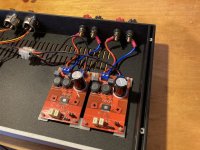
Replacing the power decoupling capacitors
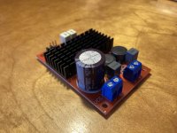
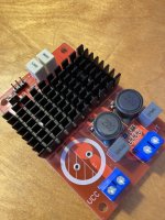
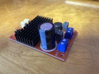
The red mono TPA3116 amplifier boards that I bought from eBay came with Nichicon 3300uF decoupling capacitors, labelled as PA(M).
Given how cheap the boards are, I was quite surprised that they used brand-name capacitors. Although I have no idea if you can tell they are genuine or not. However they are only rated for 25V. Given that I want to run them at 24V, I thought I should upgrade them.
I bought some Panasonic 3300uF / 35V capacitors (EEUHD1V332) that have the same pin-pitch. They are higher and narrower than the originals but should still fit within the 1U case.
De-soldering them and replacing them was fairly easy and I don't think I damaged the PCB in the process.
Attachments
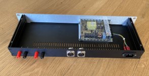
Mounted power supply
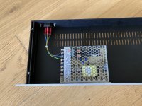
Yesterday I mounted the Mean Well power supply to the base of the case and connected it up to the IEC C14 socket.
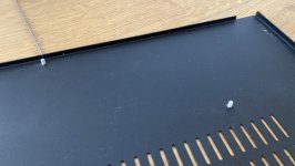
I drilled a couple of 3mm holes in the steel bottom panel of the enclosure. I was initially concerned about screws sticking out the bottom and scraping on the device below it in the rack. So I decided to try using some M3 self-clinching studs.
I inserted the studs using a 1 tonne Arbor Press. It was easy to get them to grip into the hole, but I suspect you would need a hydraulic press to get them completely flush with the sheet steel (I believe this is how they are supposed to work). But because I don't have the proper punch tools, the sheet steel did end up deforming very slightly but probably actually better to make the bottom more flush.
The screws that attach the bottom of the case stick out anyway (not sure why they aren't countersunk). So I probably could have just used screws with a flattish head anyway.
Then I wired the IEC C14 connector to the power supply using some crimp connectors at the IEC end and tinned the wires with solder at the power supply end.
I am planning to add a power indicator and mains switch to the front-panel but will do that once the rest is working.
Yesterday I mounted the Mean Well power supply to the base of the case and connected it up to the IEC C14 socket.
I drilled a couple of 3mm holes in the steel bottom panel of the enclosure. I was initially concerned about screws sticking out the bottom and scraping on the device below it in the rack. So I decided to try using some M3 self-clinching studs.
I inserted the studs using a 1 tonne Arbor Press. It was easy to get them to grip into the hole, but I suspect you would need a hydraulic press to get them completely flush with the sheet steel (I believe this is how they are supposed to work). But because I don't have the proper punch tools, the sheet steel did end up deforming very slightly but probably actually better to make the bottom more flush.
The screws that attach the bottom of the case stick out anyway (not sure why they aren't countersunk). So I probably could have just used screws with a flattish head anyway.
Then I wired the IEC C14 connector to the power supply using some crimp connectors at the IEC end and tinned the wires with solder at the power supply end.
I am planning to add a power indicator and mains switch to the front-panel but will do that once the rest is working.
Attachments
Last edited:
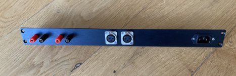
Drilled rear panel
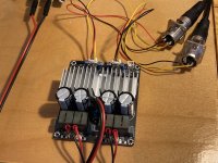
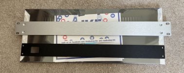
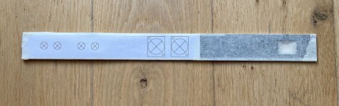
At the weekend I drilled the rear panel and mounted the connectors on it.
I started by planning the connector positioning in CAD printed and stuck it to the rear panel. I taped up any bare metal with masking tape (as recommended by rayma) to avoid scratching.
The speaker binding posts I chose have plastic insulation through the hole - I wanted to ensure they don't ground/short with the metal. They also have flattened sides - I think to help prevent rotation in the chassis. So I drilled them under size and then filed the holes to make them an oval shape. I am going to use them with 4mm banana plugs, but wanted to make sure that they would work as clamps too.
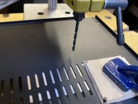
I drilled the holes for the Neutrik XLR sockets using a step drill bit.
I don't have a full size pillar drill, so had to use a battery drill with the step drill bit. It was a little bit wobbly and I wasn't prepared for the cutting speed going up, with each increase in the drill size. As a result one of the 24mm holes for the XLR is a little bit oversize.
I also clamped the aluminium a bit hard, which caused a bit for deformation.
But overall I am pretty happy with the result.
Now I just need to mount the amplifier PCBs and wire it all up!
At the weekend I drilled the rear panel and mounted the connectors on it.
I started by planning the connector positioning in CAD printed and stuck it to the rear panel. I taped up any bare metal with masking tape (as recommended by rayma) to avoid scratching.
The speaker binding posts I chose have plastic insulation through the hole - I wanted to ensure they don't ground/short with the metal. They also have flattened sides - I think to help prevent rotation in the chassis. So I drilled them under size and then filed the holes to make them an oval shape. I am going to use them with 4mm banana plugs, but wanted to make sure that they would work as clamps too.
I drilled the holes for the Neutrik XLR sockets using a step drill bit.
I don't have a full size pillar drill, so had to use a battery drill with the step drill bit. It was a little bit wobbly and I wasn't prepared for the cutting speed going up, with each increase in the drill size. As a result one of the 24mm holes for the XLR is a little bit oversize.
I also clamped the aluminium a bit hard, which caused a bit for deformation.
But overall I am pretty happy with the result.
Now I just need to mount the amplifier PCBs and wire it all up!
Attachments
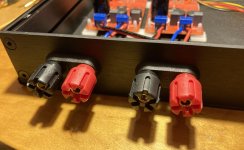
Replaced speaker binding posts
I haven't found as much time to work on this project recently and progress has slowed a bit.
I made a mistake on my choice of speaker binding posts. I was too focused on picking something that was insulated through the hole of the metal case. But they were too low quality. Both the plastic thread and metal threads started stripping when I was tightening the nuts to stop it rotating. Then the threaded metal through the middle sheared off completely on one, so I decided they were a bad purchase.
I replaced them with Cliff TP6S binding posts, which I am really happy with. They are much more solid and look better too. They are actually branded as RS Pro, not Cliff when buying from RS, but they have little Cliff logos on them.
Fortunately, I only had to do a little bit of reworking to make the new posts fit - they have a spacing of 19mm, but I had previously drilled with 20mm spacing - a little bit of filing with a metal file and they fit well. The "TPP1 terminal mounting plate" made it much easier to fit and also prevents the binding post from spinning round.
I have also been working on reducing the gain of the TPA3116 mono amplifier boards and successfully re-configured them to have a 20dB gain by removing resistor R2. The reduced a bit of hiss when the volume was turned up to full. See the other thread for details:
Reducing gain on red mono TPA3116 board?
I was also alerted to a problem with the SYNC pin being incorrectly grounded, which apparently causes the inductors to heat up. Thanks FauxFrench!
But due to the +4dBu line level that I am using, I still need to reduce the gain further. I am going to use a U-Pad resistor network to attenuate the signal by about -15dB. So that is what I am working on next...
I haven't found as much time to work on this project recently and progress has slowed a bit.
I made a mistake on my choice of speaker binding posts. I was too focused on picking something that was insulated through the hole of the metal case. But they were too low quality. Both the plastic thread and metal threads started stripping when I was tightening the nuts to stop it rotating. Then the threaded metal through the middle sheared off completely on one, so I decided they were a bad purchase.
I replaced them with Cliff TP6S binding posts, which I am really happy with
. They are much more solid and look better too. They are actually branded as RS Pro, not Cliff when buying from RS, but they have little Cliff logos on them.Fortunately, I only had to do a little bit of reworking to make the new posts fit - they have a spacing of 19mm, but I had previously drilled with 20mm spacing - a little bit of filing with a metal file and they fit well. The "TPP1 terminal mounting plate" made it much easier to fit and also prevents the binding post from spinning round.
I have also been working on reducing the gain of the TPA3116 mono amplifier boards and successfully re-configured them to have a 20dB gain by removing resistor R2. The reduced a bit of hiss when the volume was turned up to full
. See the other thread for details:Reducing gain on red mono TPA3116 board?
I was also alerted to a problem with the SYNC pin being incorrectly grounded, which apparently causes the inductors to heat up. Thanks FauxFrench!
But due to the +4dBu line level that I am using, I still need to reduce the gain further. I am going to use a U-Pad resistor network to attenuate the signal by about -15dB. So that is what I am working on next...
Attachments
Last edited:
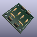
Attenuating the signal
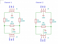
I have designed a dual-channel U-pad circuit to attenuate the signal by -15dB, based on the excellent All About Pads page by Rick Chinn.
I am going to use Vishay MRS Thin Film Resistors, which have 1% accuracy rating:
By my calculation, this resistor combination gives a value of K=5.6 and attenuation=-14.96 dB. I have tested it on a breadboard and it makes the amplifier gain much more sensible, so I can use a lot more of range on my "Passive Monitor Controller" knob.
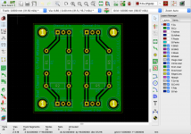
For the proper build, I designed a very simple PCB using KiCad. It was a little bit frustrating at times but overall not too hard to use. The 3D render ray-tracing feature was an added bonus that I was not expecting!
I have placed an order with JLCPCB, who are amazingly cheap compared to other PCB manufacturers who I have looked at in the past. Ordering 5x 40x40mm PCBs from them is only £1.55! But I am going to have a little bit of a wait because it is currently the Golden Week national holiday in China, plus I paid for the cheapest/slowest delivery option. The build progress shows it in a half-fabricated state at the factory . It will be interesting to see what the quality of the boards will be - it wouldn't be hard to be better than my home-made efforts of past.
While I am waiting, I am going to drill the front-panel and add a power switch and LED. I am just going to switch the Live conductor of the incoming mains. I am not experiencing any thumps or pops when turning it on/off, so I think it should be fine.
I have designed a dual-channel U-pad circuit to attenuate the signal by -15dB, based on the excellent All About Pads page by Rick Chinn.
I am going to use Vishay MRS Thin Film Resistors, which have 1% accuracy rating:
By my calculation, this resistor combination gives a value of K=5.6 and attenuation=-14.96 dB. I have tested it on a breadboard and it makes the amplifier gain much more sensible, so I can use a lot more of range on my "Passive Monitor Controller" knob.
For the proper build, I designed a very simple PCB using KiCad. It was a little bit frustrating at times but overall not too hard to use. The 3D render ray-tracing feature was an added bonus that I was not expecting!
I have placed an order with JLCPCB, who are amazingly cheap compared to other PCB manufacturers who I have looked at in the past. Ordering 5x 40x40mm PCBs from them is only £1.55! But I am going to have a little bit of a wait because it is currently the Golden Week national holiday in China, plus I paid for the cheapest/slowest delivery option. The build progress shows it in a half-fabricated state at the factory
. It will be interesting to see what the quality of the boards will be - it wouldn't be hard to be better than my home-made efforts of past.While I am waiting, I am going to drill the front-panel and add a power switch and LED. I am just going to switch the Live conductor of the incoming mains. I am not experiencing any thumps or pops when turning it on/off, so I think it should be fine.
Attachments
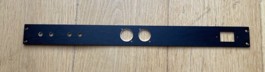
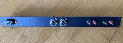
Front panel: power switch and indicator
Wow, my last post was over a month ago. I have made a little bit of progress since then.
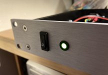
While I was waiting for the PCB to arrive from China, I decided to work on sorting out the power switch and indicator on the front panel. I wanted to try and make it look like it isn't too homemade but wanted a clean minimal look. And something to complement the brushed aluminium front panel.
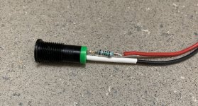
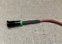
I'm not a big fan of blue LEDs, so I chose a low profile Green LED in a Black Chrome (metal) bezel as a power indicator. I really like the simplicity of the design and that it isn't made out of plastic. I put a resistor inline with the chassis mount LED, so it could be connected directly to the power supply, and then covered the resistor and solder joints with heat shrink tubing.
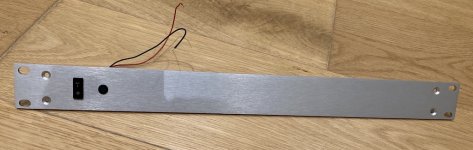
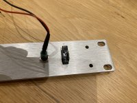
Choosing a power switch was harder. I considered a toggle switch, but I think it would have stuck out too far and maybe a bit too 1960s. So I went for a miniature slimline rocker switch, which a think looks a little bit neater than a larger rocker switch.
Cutting holes in the 4mm aluminium wasn't too bad. I drilled four holes down the length of the rectangular hole needed for the power switch and then used a fine file to get it to the right shape. The aluminium was soft enough that it was quite easy to get it to the right shape/size. I covered the panel in masking tape while I was doing this but one slip of the file did result in a small scratch on the front panel. I might use a thicker tape in future.
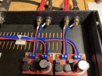
Finally, I decided the replace the crimp connectors on the speaker terminals. They were a bit chunky, which meant the wires stuck out at funny angles. I also prefer solder connections. So I bought some M5 solder lugs, which bent much better and put some heat shrink tubing over them to guard against shorting on the case. I think it looks much better than before.
Remaining tasks:
Wow, my last post was over a month ago. I have made a little bit of progress since then.
While I was waiting for the PCB to arrive from China, I decided to work on sorting out the power switch and indicator on the front panel. I wanted to try and make it look like it isn't too homemade but wanted a clean minimal look. And something to complement the brushed aluminium front panel.
I'm not a big fan of blue LEDs, so I chose a low profile Green LED in a Black Chrome (metal) bezel as a power indicator. I really like the simplicity of the design and that it isn't made out of plastic. I put a resistor inline with the chassis mount LED, so it could be connected directly to the power supply, and then covered the resistor and solder joints with heat shrink tubing.
Choosing a power switch was harder. I considered a toggle switch, but I think it would have stuck out too far and maybe a bit too 1960s. So I went for a miniature slimline rocker switch, which a think looks a little bit neater than a larger rocker switch.
Cutting holes in the 4mm aluminium wasn't too bad. I drilled four holes down the length of the rectangular hole needed for the power switch and then used a fine file to get it to the right shape. The aluminium was soft enough that it was quite easy to get it to the right shape/size. I covered the panel in masking tape while I was doing this but one slip of the file did result in a small scratch on the front panel. I might use a thicker tape in future.
Finally, I decided the replace the crimp connectors on the speaker terminals. They were a bit chunky, which meant the wires stuck out at funny angles. I also prefer solder connections. So I bought some M5 solder lugs, which bent much better and put some heat shrink tubing over them to guard against shorting on the case. I think it looks much better than before.
Remaining tasks:
- Installing the U-pad attenuator
- Earthing the case
- Adding a mains fuse
- Labelling for the front and rear panels
Attachments
- Status
- This old topic is closed. If you want to reopen this topic, contact a moderator using the "Report Post" button.
- Home
- Amplifiers
- Class D
- [Build Log] Class D amplifier in 1U rack-mount enclosure