@fauxfrench
Have you mesures the output inductors?
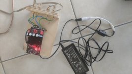
I was first between yours amp and the FR one I bought. More than twice as expensive but really good quality. No click or clock ant start-up or shutdown.
Bluetooth connection is also good.
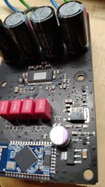
Capacitor looks to be original and no fake.
Ruby on caps seem to the also no fake")
No opamp... But symmetrical audio feed by qc3008.
Have you mesures the output inductors?
I was first between yours amp and the FR one I bought. More than twice as expensive but really good quality. No click or clock ant start-up or shutdown.
Bluetooth connection is also good.
Capacitor looks to be original and no fake.
Ruby on caps seem to the also no fake
No opamp... But symmetrical audio feed by qc3008.
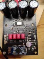
The output inductors (chokes) seem similar to those used on the "old" blue TPA3255 board. No measurements. Decent quality, not top quality. I do not say that this TPA3221 board is perfect. My initial impression is that it is a correct implementation for an 18$ TPA3221 board.
Huansueli and fauxfrench,
Thanks for your feedback.
On the boards you bought, I can see a very basic regulator (LM7805?). This type of regulator cannot suppress the noise coming for the supply, nor effectively regulate HF switching noise generated by TPA3221 itself (class d).
I wonder why these Chinese board add this component. This amp has an integrated regulator for AVDD which may be much more efficient for PSRR and load regulation!
There is indeed a 7805 on the board. I have not had the opportunity to study how the VDD, AVDD and GVDD are connected on this board. A priori, AVDD seems to be the important (low-noise) voltage while GVDD (gate-drives) is pretty unimportant (noise-wise). VDD is just input to the build-in LDO. There are no LDO performance data. To have the best control I would make my own low-noise AVDD regulator and a bulk 5V for the GVDD.
To be investigated.
To be investigated.
Yopi you're right. The 7805 goes to pin 21 true a 3.3Ohm resistor and direct to pin 22.
The trace is connecte trought a 0Ohm resistr. So it could be powerd by external regulator...
But the am has really no noise.
The trace is connecte trought a 0Ohm resistr. So it could be powerd by external regulator...
But the am has really no noise.
Attachments
I am currently analyzing the board I mentioned in posting #16. The general amplifier circuit is close to identical to the schematic (Figure 50) recommended by TI in the datasheet. Only some decoupling capacitors are 100nF where TI suggests 1uF. The layout seems sensible. Gain 24dB.
BUT, I am still trying to find my way around in a start-up circuit controlling the /RESET and /CMUTE control pins. The components used for this are several and very small, and the connections difficult to follow. On top, the marking of a SOIC-8 IC has been removed. My first quick test of the board indicated that this circuit did not leave very good results ("loud click").
I will continue my struggle and present a schematic once the circuit is known in full.
Last edited:
Hi
actually i try out some class a amp (ACA) but maybe this thread is interesting for you:
https://www.diyaudio.com/forums/cla...ro-ua801x-al-inductors-etc-2.html#post5661406
chris
actually i try out some class a amp (ACA) but maybe this thread is interesting for you:
https://www.diyaudio.com/forums/cla...ro-ua801x-al-inductors-etc-2.html#post5661406
chris
Could this be an attiny25/45 or 85? That is the one I useOn top, the marking of a SOIC-8 IC has been removed.
Hi Chris,
Right, winter is the time to try-out class A designs. In the snow-covered Austrian landscape there is suddenly a house where the snow is gone and the spring-flowers start appearing in the garden. The house of the family with a class A amplifier.
Enjoy the sound (and heat) .
.
Thanks for the link to the other thread. Abraxalito has before mentioned that the TPA3220 has potential (when properly decoupled) and TPA3221 seems very close family. My confidence in Abraxalito's views is very high.
I bought this board because of its availability and price. I remain a value-for-money spirit and overall I am not disappointed with the board. If my first impression of this start-up circuit remains unchanged, I just notice that problems start appearing on such price-attractive boards the moment the guidance in the datasheet is not followed.
Right, winter is the time to try-out class A designs. In the snow-covered Austrian landscape there is suddenly a house where the snow is gone and the spring-flowers start appearing in the garden. The house of the family with a class A amplifier.
Enjoy the sound (and heat)
.Thanks for the link to the other thread. Abraxalito has before mentioned that the TPA3220 has potential (when properly decoupled) and TPA3221 seems very close family. My confidence in Abraxalito's views is very high.
I bought this board because of its availability and price. I remain a value-for-money spirit and overall I am not disappointed with the board. If my first impression of this start-up circuit remains unchanged, I just notice that problems start appearing on such price-attractive boards the moment the guidance in the datasheet is not followed.
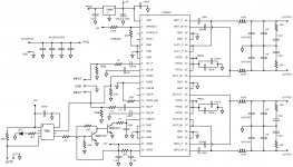
My first draft of the TPA3221 board (posting #16) schematic.
The deviation from the TI recommended circuit is the four 100nF capacitors (decoupling) connected to PVDD pins on the TPA3221 IC. TI recommends four 1uF.
Else, the new but perhaps not very successful circuit-part is the start-up circuit with the 8-pin "TBD" (To Be Decided) IC and the two NPN transistors. The "TBD" IC I haven't figured out yet. Bucks bunny helpfully suggested if it could be an 8-pin Attiny micro-controller but that does not fit with the power terminals. My guess is that it is a voltage monitor circuit (watch-dog) used for cheap micro-controller purposes. Of those there are hundreds of versions.
Later I will test the start-up circuit again with different supply voltages and if it still does not perform well, I will try to suggest an improvement.
Attachments
I am through with designing some power-management around TPA3255 using Attiny25 and other stuff. If you are interested you may start another thread and I will chime in.Later I will test the start-up circuit again with different supply voltages and if it still does not perform well, I will try to suggest an improvement.
Hi bucks bunny,
At present I am caught-up with some urgent tasks for some weeks at least.
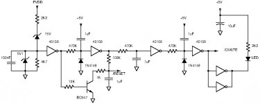
I studied the TPA3221 datasheet and concluded that the following sequence should be followed during start-up:
* Detect the supply voltage (PVDD).
* Turn /RESET high after the supply voltage has reached a safe operating level.
* Use a delay from when /RESET is let high until /CMUTE is also turned high.
I drafted a sequential start-up circuit using a CD40106 inverting Schmitt trigger. The first stage acts as a voltage detector changing state around a supply voltage of around 18V. Following a delay /RESET is pulled high. After a further delay /CMUTE is allowed high.
I like to try this circuit out but for the time being I haven't got time.
Your idea to use an 8-pin ATTINY microcontroller is very good. I would just like to check if the sequence I assume valid is in reality successful.
I will return when time allows.
At present I am caught-up with some urgent tasks for some weeks at least.
I studied the TPA3221 datasheet and concluded that the following sequence should be followed during start-up:
* Detect the supply voltage (PVDD).
* Turn /RESET high after the supply voltage has reached a safe operating level.
* Use a delay from when /RESET is let high until /CMUTE is also turned high.
I drafted a sequential start-up circuit using a CD40106 inverting Schmitt trigger. The first stage acts as a voltage detector changing state around a supply voltage of around 18V. Following a delay /RESET is pulled high. After a further delay /CMUTE is allowed high.
I like to try this circuit out but for the time being I haven't got time.
Your idea to use an 8-pin ATTINY microcontroller is very good. I would just like to check if the sequence I assume valid is in reality successful.
I will return when time allows.
Attachments
Last edited:
Today I made a brief test of start-up of the board. Inputs shorted to signal ground through 220 Ohm. 12V/15V/16V/19V/24V and 30V supply voltages. 3-5 start-up sequences for each supply voltage. With 12V supply, no start-up noise. With 15V supply, very little start-up noise. With 16V supply, start-up noise easily detectable. With 19V supply, clear start-up noise. With 24V supply, firm start-up noise. With 30V supply, firm start-up noise.
It is not that the noise will put the speakers at risk or will cause a nervous breakdown for the family dog. My criticism is that the designer(s) has added considerable amounts of components to avoid such noise but has failed. That there is substantially no noise below 15V supply is no solution - who buys a TPA3221 board to run it below 15V supply?
No shut-down noise.
With better time I will try to implement my own sequential design.
Last edited:
Today I made a brief test of start-up of the board. Inputs shorted to signal ground through 220 Ohm. 12V/15V/16V/19V/24V and 30V supply voltages. 3-5 start-up sequences for each supply voltage. With 12V supply, no start-up noise. With 15V supply, very little start-up noise. With 16V supply, start-up noise easily detectable. With 19V supply, clear start-up noise. With 24V supply, firm start-up noise. With 30V supply, firm start-up noise.
It is not that the noise will put the speakers at risk or will cause a nervous breakdown for the family dog. My criticism is that the designer(s) has added considerable amounts of components to avoid such noise but has failed. That there is substantially no noise below 15V supply is no solution - who buys a TPA3221 board to run it below 15V supply?
No shut-down noise.
With better time I will try to implement my own sequential design.
Well, i'm eyeing this amp as an option for an off-grid amp (solar powered, so only 12V DC) to power some efficient Fane 12-250TC speakers, so color me curious
But i don't think that's what you meant...By the way, any opinion on requirements for front end for this? Is a volume pot good enough, or does it need a buffer/pre in front?
- Home
- Amplifiers
- Class D
- TPA3221