The left one's connected all right just via a net name (VDDA) rather than an explicit wire so as to render the schematic a tad less cluttered. If you look at the DS for TDA8932 you'll see the manufacturer's recommendation for pin8 is to be fed from the main supply via 10R/100n as filtering. Turns out this doesn't give a clean enough supply - that's where the LM317 comes in - it supplies a clean low impedance rail for the signal stages of the amp.
There is a caveat though - this supply can't be allowed to go more +ve than the main (output stage) rail. So when the two are fed from separate regs a diode is needed between the two to prevent this condition. Naturally enough i blew up a few chips before I discovered this. The U4 reg provides a low impedance supply to the output stage rendering the quality of the feeding supply largely irrelevant.
There is a caveat though - this supply can't be allowed to go more +ve than the main (output stage) rail. So when the two are fed from separate regs a diode is needed between the two to prevent this condition. Naturally enough i blew up a few chips before I discovered this. The U4 reg provides a low impedance supply to the output stage rendering the quality of the feeding supply largely irrelevant.
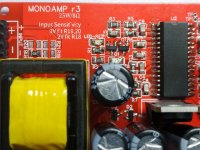
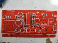
r3 PCBs arrived
Apologies that there will be a couple of days' delay in getting the ordering of kits open - some caps proved a little difficult to source.
The input sensitivity (either 1V or 2V) is set by the resistors near the input. Default is 2V with R18 fitted. For 1V sensitivity (to drive from a mobile phone for example) then fit R19 & R20. R21 is a band-aid (aka 'ground lifter') if there's no other way to reduce common-mode voltage variations between source and amp. Best is to connect the 0V of your source to the 0V (power input) of this amp via a dedicated wire. If that's impossible or impractical, then R21 may be fitted with a 10R to reduce the CM voltage between the two. Without a conductive path between source and amp there may well be low level hum as the CMRR of the transformer isn't perfect.
While we're on the subject of transformers there's another caveat - they don't like DC at all, not even a few mV. So AC coupling is a requirement to the input of this amp, I usually use an electrolytic. If you choose an overly small valued cap there's the chance of introducing some bass-boost, which may (or may not) be desirable. I will run some sims to give an indication of the values of coupling cap which might be gainfully employed.
There are two LEDs, one yellow - for power, and the other is red, to indicate a fault. On power up (from 24V), they both come on and if all is fine, the red one goes off after less than 1s. The TDA8932 is very well behaved as regards pops and clicks, nothing noticeable on powerup/powerdown on any of the prototypes I've built so far. The amp will work down to around 12V supply but will have reduced power output and poorer SQ as the supplies won't be regulated. Of course it can be modded to regulate at 12V by substituting the zeners (D2-D5) for lower voltage ones.
Attachments
While we're on the subject of transformers there's another caveat - they don't like DC at all, not even a few mV. So AC coupling is a requirement to the input of this amp, I usually use an electrolytic. If you choose an overly small valued cap there's the chance of introducing some bass-boost, which may (or may not) be desirable. I will run some sims to give an indication of the values of coupling cap which might be gainfully employed.
As a result of running some LTSpice simulations I've now determined that the minimum value electrolytic for AC coupling is 22uF with 2V sensitivity setting. On 1V sensitivity the input inductance is lower necessitating a 100uF. These are minimums, feel free to go higher.
The bass boost idea doesn't look very practical as when the coupling cap is undersized the peak is quite sharp - i.e. the resonance is fairly high Q.
I use transformer at input because i do not want to use capacitor on input.
There we differ - I don't mind capacitors its just that transformers provide isolation from CM noise (generated by the amp's SMPSU) and capacitors don't. The primary reason for the trafo is to defeat the CM noise.
Transformers can deal good with DC.
In my understanding no signal transformers like DC - the transformer here clearly falls into the 'signal' category. There are some particular applications - normally power, rather than signal - where transformers need to cope with DC - for example in OPTs in valve amps - and there are well-worn methods for dealing with those. One is use of a gapped transformer - by introducing an air-gap into the core the tendency to saturate can be reduced. Another is winding a transformer with a centre tap to run in push-pull mode where the currents in the two half-windings cancel each other out. The cancellation may not be total so gapping might be used in addition. Gapping can be used where sacrificing shunt inductance isn't a big deal.
Neither of these mitigating strategies are appropriate in this signal application where shunt inductance is crucial as the transformer needs to provide the lightest possible loading on the source.
PSU
Hi Richard,
as I am expecting the amps to be delivered soon, I think about the PSU. How sensitive to the psu quality is the amp and what should bei the power capacity for one? Does using 2 PSUs give any advantage?
there are so many SMPS on the market....... is any Meanwell 24V 50W PSU ok?
Thanks and best regards
Ernst
Hi Ernst
Your amps seem to have gotten held up, no information as to what's happened to them so far.
As for the PSU - the amps have regulators on-board with the aim of making the PSU quality much less important than with an amp with unregulated power. The power capacity I aim for is around 2.5A peak current (with an 8ohm load). So typically the PSU rating will be about 60W per channel (24V * 2.5A).
Meanwell is a top-tier Taiwanese SMPSU brand so will most likely work fine.
") .
. Jonesing for a project and this one looks right up my alley. (I have a few cheap 8932 boards but never did anything with them and have done lots of through hole but no SMD yet). Anyone have any advice on SMD? Plan to go the tweezer and iron method but not opposed if there are better ways.
Sam - when you say you're 'Jonesing for a project' do you mean you want to build these amps yourself? All the parts are available except for the transformers which I had made especially for this design. The gerbers are available too when I get around to putting them up.
As for SMD advice, I'm still using the tweezers and iron route. The PCB manufacturer we use has a nice service of stuffing the board but its only really practical if they stock the parts which are needed and I don't think TDA8932 is on their shelves. But getting them to put resistors and some caps (they don't do NP0 above 220pF) down could be a time saver.
As for SMD advice, I'm still using the tweezers and iron route. The PCB manufacturer we use has a nice service of stuffing the board but its only really practical if they stock the parts which are needed and I don't think TDA8932 is on their shelves. But getting them to put resistors and some caps (they don't do NP0 above 220pF) down could be a time saver.
Thanks Richard. Very much open to buy boards already stuffed if you have some. I am not that hard core LOL. Semi stuffed also works.
I hung out in the subwoofer or speaker forums a long time and new to amplification. I have a large format horn setup now and feel it is time to improve other areas of my signal chain. I realize everyone has their opinion but would value anyone's input on my situation. Active vs passive. My HF horns need CD EQ. I currently use passive XO with CD EQ from my power amp. I am contemplating going active on XO and biamp via Dayton 408 but also interested in considering passive options. That is what I am researching now. Apparently I need a zobels or LCR circuit for 6db CD EQ. Very much unchartered territory for me. Love learning though and enjoy a good challenge. On the other hand, I am not going to spend ridiculous sums of money for large passive parts. I am leaning on active but admit I drool over the sexy Class A and esoteric amp designs like Jfet. That said, the large TDA8932 thread really got me interested in Class D but admit all the modding needed for the china boards is over my head and so here we are... I very much like supporting DIY designers such as yourself making their designs available to those less knowledgeable. Thanks
I hung out in the subwoofer or speaker forums a long time and new to amplification. I have a large format horn setup now and feel it is time to improve other areas of my signal chain. I realize everyone has their opinion but would value anyone's input on my situation. Active vs passive. My HF horns need CD EQ. I currently use passive XO with CD EQ from my power amp. I am contemplating going active on XO and biamp via Dayton 408 but also interested in considering passive options. That is what I am researching now. Apparently I need a zobels or LCR circuit for 6db CD EQ. Very much unchartered territory for me. Love learning though and enjoy a good challenge. On the other hand, I am not going to spend ridiculous sums of money for large passive parts. I am leaning on active but admit I drool over the sexy Class A and esoteric amp designs like Jfet. That said, the large TDA8932 thread really got me interested in Class D but admit all the modding needed for the china boards is over my head and so here we are... I very much like supporting DIY designers such as yourself making their designs available to those less knowledgeable. Thanks
Only yesterday we got the first part-stuffed boards back from the PCB house. There are only a few SMD parts needed to be added - NP0 caps, a resistor and two diodes plus the TDA IC. My job for this week is to build one up to verify we got the BOM right.
The commercial thread for this design is here : Transformer-fed TDA8932 25W/8R mono amp kits
If anyone wants to build their own, I've attached the zipped up gerber files for the PCB.
The commercial thread for this design is here : Transformer-fed TDA8932 25W/8R mono amp kits
If anyone wants to build their own, I've attached the zipped up gerber files for the PCB.
Attachments
Last edited:
I've decided to use the new build as a test bed for some COTS (commercial off-the-shelf) transformers I have found which are quite a close match for the custom ferrite ones. A pair of these are on order :
2PCS / 600:20K audio cattle imports permalloy audio transformer audio balance unbalanced conversion|audio transformer|transformer audiotransformer permalloy - AliExpress
As ever, I'm curious to know if permalloy sounds any better than 10k ferrite. The primary inductance (from the vendor's Taobao page, its not shown on the Aliexpress page) looks a lot higher which is potentially good news for anyone who doesn't like using an electrolytic for DC blocking. A film cap looks likely to be practical, I'll try that out and report back.
- Home
- Amplifiers
- Class D
- Transformer input TDA8932 mono amp