Member
Joined 2018
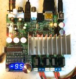
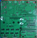
I started TI TAS6422 2.1MHz Class-D Digital Amp Project.
An original designed board has PCM9211 for 24bit 96kHz ADC, Coax/Optical SPDIF, I2S and LVDS-I2S interfaces controlled with PIC16F1829. One-button & Rotary Encoder UI software is now under development. I will put my source code on my Github repository soon. I'd like to share my design information and impressions for all DIY'er members.

My Project Web Page: TAS6422 Amprefire Fix & Modification
Best Regards,
CyberPit
An original designed board has PCM9211 for 24bit 96kHz ADC, Coax/Optical SPDIF, I2S and LVDS-I2S interfaces controlled with PIC16F1829. One-button & Rotary Encoder UI software is now under development. I will put my source code on my Github repository soon. I'd like to share my design information and impressions for all DIY'er members.
My Project Web Page: TAS6422 Amprefire Fix & Modification
Best Regards,
CyberPit
Attachments
Member
Joined 2018
Hi AIM65-San,
Thanks, responding
I compared it with my TPA3116D2 PBTL amplifier. I just listen a few minutes as of now.
The first impression is smooth Hiss sound, but it keeps clear edges even in the small SPL. Of course, there's no hum nor white noises with a digital connection path at any volume setting. Embedded ADC sound feels some soft than a digital path, but It seems not so bad. I will check audio performances with my USB-Audio device later.
Member
Joined 2018
Currently, I'm writing a code for PIC18F1829. Today, the code size exceeds 98% of its capacity. Volume control, Balance, Souce Selection menu had implemented, but I want to implement the following optional parameters...
- HPF OFF/ON with Cut-off frequency selection
- I2S Header Input/Output direction selection
- ADC sampling frequency Selection (96kHz/48kHz)
- Optical DIT output source selection (optional)
- DC/AC Load diagnostics (optional)
- ADC signal detection threshold level setup(optional)
CyberPitさん、こんにちは。
とても面白そうなプロジェクトですね。
私が日本語のページを紹介する時は、Google翻訳のリンクも一緒に含めるようにしています。
英語は苦手なのですが、大体意味が通じるように訳されているのではないかと思います。
Google translated project page:
TAS6422 Class-D 2.1MHz Switching Full Digital Amplifier (Under Construction)
Google Translate
とても面白そうなプロジェクトですね。
私が日本語のページを紹介する時は、Google翻訳のリンクも一緒に含めるようにしています。
英語は苦手なのですが、大体意味が通じるように訳されているのではないかと思います。
Google translated project page:
TAS6422 Class-D 2.1MHz Switching Full Digital Amplifier (Under Construction)
Google Translate
Last edited:
Member
Joined 2018
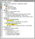
XC8 Optimized for Size
Hi Reactance-San,
Thank you, I forgot to use that option. Now it's usable in the free edition!

The result was 95% --> 88%
(-2 and -s were the same)
Now I can continue writing code for a while.
This weekend, I will go to "Akihabara" to buy a PIC16F18346-I/P.
The retail price of PIC16F18346-I/P is 16% cheaper than PIC16F1829 even twice capacity. There's no reason to migrate
if you using XC8 try to compile using -2 to reduce code size or use assembly.
Hi Reactance-San,
Thank you, I forgot to use that option. Now it's usable in the free edition!
The result was 95% --> 88%
(-2 and -s were the same)
Now I can continue writing code for a while.
This weekend, I will go to "Akihabara" to buy a PIC16F18346-I/P.
The retail price of PIC16F18346-I/P is 16% cheaper than PIC16F1829 even twice capacity. There's no reason to migrate
Attachments
Member
Joined 2018
CyberPitさん、こんにちは。
とても面白そうなプロジェクトですね。
私が日本語のページを紹介する時は、Google翻訳のリンクも一緒に含めるようにしています。
英語は苦手なのですが、大体意味が通じるように訳されているのではないかと思います。
Dear WWWWW11-San,
Thank you for adding the machine translation link.
I fully agree with you, It's better to have a link for all members.
Hi Reactance-San,
Thank you, I forgot to use that option. Now it's usable in the free edition!
View attachment 860601
The result was 95% --> 88%
(-2 and -s were the same)
Now I can continue writing code for a while.
This weekend, I will go to "Akihabara" to buy a PIC16F18346-I/P.
The retail price of PIC16F18346-I/P is 16% cheaper than PIC16F1829 even twice capacity. There's no reason to migrate
Just last week I started using PIC's again after I got a deal with an ICD4, 8-bit stuff is just simple no need for complex ARM32-bit stuff, the datasheets are clean logical register layout easy to use.
Member
Joined 2018
Distortion Check Result
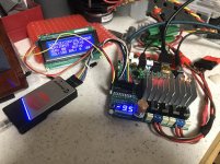
Here are some Audio performance check results.
Simply checked with 44.1kHz 24bit Optical S/PDIF feed to my TAS6422 Amp which loading 8homs dummy load.
Measured with E-mu USB0404 with Balanced Attenuator.
DC 16V Power Supply used this time. Consuming current was appx. 450mA@IDLE State. Heat sink temperature was considerably raised high. I felt this size heat sink was the right choice.
Measurement System Line Through Performance

1kHz@44.1kHz Sampling Distortion Near Clipping Level

1kHz@44.1kHz Sampling -16dB Below Clipping Level

Small SPL distortion performance was quite good enough for my desktop Audio system. I will check with my 24V power supply and cooling fans later.
Here are some Audio performance check results.
Simply checked with 44.1kHz 24bit Optical S/PDIF feed to my TAS6422 Amp which loading 8homs dummy load.
Measured with E-mu USB0404 with Balanced Attenuator.
DC 16V Power Supply used this time. Consuming current was appx. 450mA@IDLE State. Heat sink temperature was considerably raised high. I felt this size heat sink was the right choice.
Measurement System Line Through Performance
1kHz@44.1kHz Sampling Distortion Near Clipping Level
1kHz@44.1kHz Sampling -16dB Below Clipping Level
Small SPL distortion performance was quite good enough for my desktop Audio system. I will check with my 24V power supply and cooling fans later.
Member
Joined 2018
Is TAS6422 Very Cool! or Hot! !!??
Maybe, I need to mention the heat of this chip. TAS6422 sounds good enough and smooth like analog amplifiers. But I can't say "It's Cool!" because "it's Very Hot" as actual analog amplifiers. The consuming total current at the stand-by state of this board is 65mA. (The other part is fully working except TAS6422)
In running idle consuming total current at 16.5V Power supply is 455mA. This means almost 6.5W of heat should radiate from Heatsink. Actually, the Heatsink on my board temperature indicator shows 57 degrees in my room atmosphere 26 degrees.

The datasheet graph indicates PVDD idle current at 16.5V supply is 37mA around, plus VBAT 80mA and some VDD (15mA, 3.3V) total 170 - 200mA consuming normally. But my board consuming almost twice idling power!
I'm wondering something wrong on my TAS6422 chip. (But it looks working normally, No warning flags comes from TAS6422)
One more concern about heat is the output power efficiency. Datasheet shows 65%@5W, 75%@18W, 80%@40W around.
Considering the above things totally, maybe I need to add cooling Fan for Full power operation with 24V power supply anyway...
Maybe, I need to mention the heat of this chip. TAS6422 sounds good enough and smooth like analog amplifiers. But I can't say "It's Cool!" because "it's Very Hot" as actual analog amplifiers. The consuming total current at the stand-by state of this board is 65mA. (The other part is fully working except TAS6422)
In running idle consuming total current at 16.5V Power supply is 455mA. This means almost 6.5W of heat should radiate from Heatsink. Actually, the Heatsink on my board temperature indicator shows 57 degrees in my room atmosphere 26 degrees.
The datasheet graph indicates PVDD idle current at 16.5V supply is 37mA around, plus VBAT 80mA and some VDD (15mA, 3.3V) total 170 - 200mA consuming normally. But my board consuming almost twice idling power!
I'm wondering something wrong on my TAS6422 chip. (But it looks working normally, No warning flags comes from TAS6422)
One more concern about heat is the output power efficiency. Datasheet shows 65%@5W, 75%@18W, 80%@40W around.
Considering the above things totally, maybe I need to add cooling Fan for Full power operation with 24V power supply anyway...
Last edited:
Member
Joined 2018
Be Cool!!
I built another TAS6422 board to evaluate the power consumption issue.
That was not hot than the previous one. Consuming the idle current was 165mA@16.5V power supply. I checked the issued board very carefully, Finally I found a crack on the Bootstrap Capacitor. It might be damaged during my performance measurement or PWM waveform probing situation. I replaced the cracked capacitor, then the heat sink temperature decreases to 36 degrees around. Lossing power of idling heat belows 3watts, so maybe I can reduce the size of the heatsink some.
Now I can say TAS6422 is a Cool designed device anyhow!
Member
Joined 2018
Version 0.2 Released
I just finished working on version 0.2 board Design and software development.
GitHub URL: GitHub - CyberPit/TAS6422-AMP-Project: 2.1MHz switching Class-D Audio Amplifire Project
Project WebPage:TAS6422 Amprefire Fix & Modification
Machine Translation URL: Google 翻訳
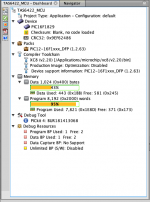
This is the final release for version 0.2 Board. 99% PIC16F1829 programming area had used with this release (Optimized =2)
The following features are implemented...
Known Issue:

PIC16F18346 software will be developed only for the version 0.3 board(Maybe... Not Sure)
I just finished working on version 0.2 board Design and software development.
GitHub URL: GitHub - CyberPit/TAS6422-AMP-Project: 2.1MHz switching Class-D Audio Amplifire Project
Project WebPage:TAS6422 Amprefire Fix & Modification
Machine Translation URL: Google 翻訳
This is the final release for version 0.2 Board. 99% PIC16F1829 programming area had used with this release (Optimized =2)
The following features are implemented...
- Volume Control (0.5dB Step)
- Source Selection (ADC, OPT, COAX, LVDS, I2S)
- Balance Setup
- AUX Header direction Setup (I2S IN/OUT)
- Optical Output (Same content as selected source)
- Debug Monitor I2C 20x4 LCD Display Driver
- Back-up Settings (Source, Balance, I2S Direction)
Known Issue:
- Version 0.2 board ADC input L/R should be swapped
PIC16F18346 software will be developed only for the version 0.3 board(Maybe... Not Sure)
Member
Joined 2018
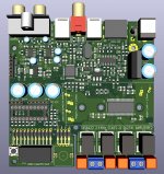
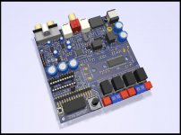
Embedded Features
The Feature Layout of version0.2 TAS6422 AMP Board
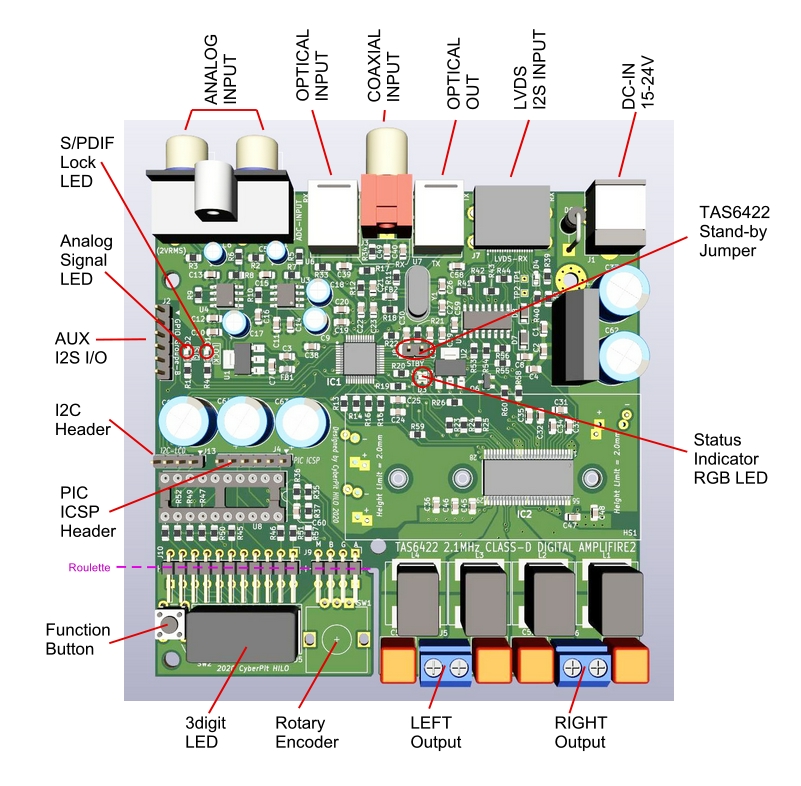
Next version 0.3 will change MCU, Voltage Regulator, Stand-by actions, Parameter Setups. It should be take a while...
I'm wondering, Which is important? LVDS I2S INPUT or COAX OUTPUT (Board Space is limited...) Or both are not required?
The Feature Layout of version0.2 TAS6422 AMP Board
Next version 0.3 will change MCU, Voltage Regulator, Stand-by actions, Parameter Setups. It should be take a while...
I'm wondering, Which is important? LVDS I2S INPUT or COAX OUTPUT (Board Space is limited...) Or both are not required?
Member
Joined 2018
Audio Performance Checked
I measured some Audio Performances.
Top to Down, Left to Right.
- My Measurement System Emu-0404USB Line Thru Performance

- PCM9211 ADC to SPDIF-OUT
(-24dB F.S.) (-2dB F.S.)


Large Swing distortion performance is not good. Input voltage divider circuit might be a reason. Should be investigate later.
- Power Bandwidth (SPDIF to SPEAKER-OUT)
(10.7Vrms into 8 ohms) (10.7Vrms into 4ohms)


Totally flat!
- Power Amplifier Distortion (SPDIF to SPEAKER-OUT)
(1.5Watts into 4ohms) (28Watts into 4ohms)


Distortion level is very small in nominal listening level.
Especially, remain noise level is very small !
Sound impressions:
Sound-stage images very steady. No moving feels. A high frequency range metal percussion such as triangle, tambourines, ride-cymbals sounds clearly like a conventional amplifiers ( Most of class-D amplifier rings like a crashed tones) Tone colors are not change even in very small SPL midnight listening. ADC input S/N is high enough, but sounds is not so clear enough for me as of now. Digital connected source are O-Kay.
I measured some Audio Performances.
Top to Down, Left to Right.
- My Measurement System Emu-0404USB Line Thru Performance
- PCM9211 ADC to SPDIF-OUT
(-24dB F.S.) (-2dB F.S.)
Large Swing distortion performance is not good. Input voltage divider circuit might be a reason. Should be investigate later.
- Power Bandwidth (SPDIF to SPEAKER-OUT)
(10.7Vrms into 8 ohms) (10.7Vrms into 4ohms)
Totally flat!
- Power Amplifier Distortion (SPDIF to SPEAKER-OUT)
(1.5Watts into 4ohms) (28Watts into 4ohms)
Distortion level is very small in nominal listening level.
Especially, remain noise level is very small !
Sound impressions:
Sound-stage images very steady. No moving feels. A high frequency range metal percussion such as triangle, tambourines, ride-cymbals sounds clearly like a conventional amplifiers ( Most of class-D amplifier rings like a crashed tones) Tone colors are not change even in very small SPL midnight listening. ADC input S/N is high enough, but sounds is not so clear enough for me as of now. Digital connected source are O-Kay.
Member
Joined 2018
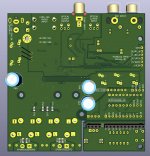
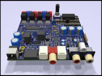
New version Board Arrived
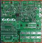
A new version 0.3 board had arrived. I ordered this PCBA to JLPCB, it costs around $60 with 10pcs boards.
Change points are...

GitHub URL: GitHub - CyberPit/TAS6422-AMP-Project: 2.1MHz switching Class-D Audio Amplifier Project
Project WebPage:TAS6422 Amplifier Project
Machine Translation URL: Google Translated Link
A new version 0.3 board had arrived. I ordered this PCBA to JLPCB, it costs around $60 with 10pcs boards.
Change points are...
- Add IR-Remote Receiver
- TAS6422 Stand-by Control by PIC
- Change voltage regulator devices
- Modified some parts layouts
GitHub URL: GitHub - CyberPit/TAS6422-AMP-Project: 2.1MHz switching Class-D Audio Amplifier Project
Project WebPage:TAS6422 Amplifier Project
Machine Translation URL: Google Translated Link
Attachments
Last edited:
I see a few PIC users but not so many threads and posts with much useful info to help noobs get going with one.
I was wondering, since there is mention of PICs here, if there are any crackerjack PIC programmers who could help with assembly programming a bit. Just help to get passed some blockages, like how to properly include library, set up config bits and things like that.
I'm on mac, using mplabx and I don't want to use C, just assembly, and the PIC is a 16F688 (PDIP14).
One thing that could be done is dedicate a thread for that, so other noobs could also find some guidance specific to programming PICs...
Member
Joined 2018
Is Time (Spending) Money?
Hi spookydd-San,
I also using MPLABx on my iMac.
I'm writing with C Language from the point of view of Potability and Readability. Sometimes (i.e. ISR routines or critical timing part) need to use Assembler language anyway, but it's a very rare case in today. Especially PIC devices are reasonable price even in 32bit core devices. I prefer to pay some costs for shorten a time.
Last edited:
Very spiffy design by the way. Very nice. Although totally out of reach for a diyer such as muself, who can't touch anything SMT, unfortunately.
Anyway, I won't be doing any C programming at all, just plain assembly only, and right now the project I'm working on is based on the 16F688.
I have the whole tool chain pretty much working: Mac/mplabx/pickit3/assembler
And I was able to program a small hex file I found but didn't program or compile, into a 12F629, with some leds, to make them blink. So I know what I have works.
But now I need to get going with programming, and I'm bumping against a few hurdles, so that's why I'm reaching out for some pointers..
- Status
- This old topic is closed. If you want to reopen this topic, contact a moderator using the "Report Post" button.
- Home
- Amplifiers
- Class D
- TAS6422 2.1MHz Class-D Digital Amp Project