
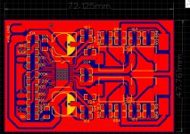
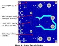
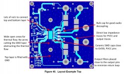
Ceramic decoupling caps are too far from the chip - as close as possible.. More of them would be good, electrolytic isn't going to be so effective at these frequencies, and has much more stray inductance. The power routing is odd, you go all the way round the houses
rather than route direct on the underside. That big loop is coupling direct into the input side too - power wiring should be on the output side.
rather than route direct on the underside. That big loop is coupling direct into the input side too - power wiring should be on the output side.
Last edited:
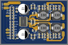
Yes, the ceramic decoupling capacitors are further out than the electrolytic... This is really not ideal, the extra inductance will greatly diminish their effectiveness.
Also, as chip caps can have rather high Q, there is the possibility of nasty oscillations with the extra inductance. They can also oscillate with the elecs if they are low ESR, but that's something that needs to be checked on an actual prototype. Push out those electros and bring in the chip cap.
Mark's point is good. I did not spot that, although it might work out as the signal pairs are routed together. An option might be to try small series resistors on the power bus, before the electros. However, I doubt it will work that well at audio frequencies. You can compute the resulting attenuation and see if it is worth it. It seems you are shorting one input, is it on purpose? If yes, than why bother with the input caps? Finally, why are you ground referencing the inputs?
- Status
- This old topic is closed. If you want to reopen this topic, contact a moderator using the "Report Post" button.
- Home
- Amplifiers
- Class D
- TPA3118 D2 amplifier class D