Those diodes clamp any voltage spikes to either ground or to the positive rail (depending on the polarity of the spike) and so prevent the output pin of the IC being taken either above the supply voltage or below ground potential which could damage it.
The type of diode is not critical but it must be a fast switching type and have a voltage rating equal to at least twice the DC supply voltage plus a safety margin. The current handling needs to be at least a couple of amps or more.
Just try whatever you can get that matches that requirement.
I will try buy the schottky diode SMD SS86, my power supply module is 36 5A (cheap module from eBay). I hope this diode fix the problem, it's rated for 8A 60v. If doesn't solve this, maybe the IC TDA7498E is damaged, or some other problem, of which I have no knowledge to identify it. In any case the seller has already sent a replacement module, now I just have to wait.
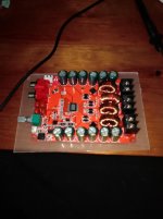
Attachments
Let us know your opinion when you get them working.
I'm thinking of just such a module to re-purpose an old amp - the high (for a class D board) supply voltage suits my existing transformer.
When this amplifier board or the new replacement board i will receive work, i will post my opinion about that.
I will try buy the schottky diode SMD SS86, my power supply module is 36 5A (cheap module from eBay). I hope this diode fix the problem, it's rated for 8A 60v. If doesn't solve this, maybe the IC TDA7498E is damaged, or some other problem, of which I have no knowledge to identify it. In any case the seller has already sent a replacement module, now I just have to wait.
OK
") and good luck. Remember, those diodes aren't really doing much in normal operation, they are just for protection.
and good luck. Remember, those diodes aren't really doing much in normal operation, they are just for protection.If the diode has failed short circuit then it could be quite likely the chip has failed as well.
OK
If the diode has failed short circuit then it could be quite likely the chip has failed as well.
I can't identify if my IC TDA7498E is already failed or not, because i don't see any visible damage on it.
How can i test my IC TDA7498E first with DMM?
Can you explain me?
If my IC TDA7498E is already failed and damage, so it would be pointless to spend money on the schottky diode.
How can i check this PIN 20 & PIN 21?
Remove heatsink and check volt.I think your IC not damaged
** supply should be 12v~24v max. without heatsink (don't connect 36v)
PIN 29(SVR) connected one capacitor 10uF(smd) replace with new(10uF~22uF). it will work
Regards
MANOJ
Remove heatsink and check volt.I think your IC not damaged
** supply should be 12v~24v max. without heatsink (don't connect 36v)
PIN 29(SVR) connected one capacitor 10uF(smd) replace with new(10uF~22uF). it will work
Regards
MANOJ
How can i check my IC with DMM?
How can i find the PIN 29(SVR)?
Can you give me an help?
Best regards.
Remove heatsink and check volt.I think your IC not damaged
** supply should be 12v~24v max. without heatsink (don't connect 36v)
PIN 29(SVR) connected one capacitor 10uF(smd) replace with new(10uF~22uF). it will work
Regards
MANOJ
Dear NANOJ, i hope you have an nice day.
If i'm not wrong reading the circuito, this capacitor you say is on the position C16 of the circuito, right?
I test it with my DMM and this is not damage.
It's seem to be another problem for this board only work for only 15min.
My knowledge is not to much and i will pass this, but when i receive the new replacement board from the seller, i hope it work without any problem.
If i'm not wrong reading the circuito, this capacitor you say is on the position C16 of the circuito, right?
I test it with my DMM and this is not damage.
PIN-29 check the volt with DMM it should be 1.8v~2v if not replace capacitor with new
Regards
MANOJ
PIN-29 check the volt with DMM it should be 1.8v~2v if not replace capacitor with new
Regards
MANOJ
Do i need power up the TDA7498E with 12v or 24v for test because i need remove the heatsink, you say this in other post, right?
For measure the PIN29 i need the DMM and connect the black terminal on GND in of the power supply of TDA7498E board and the red terminal on PIN29, right?
yes and PIN 21,22 also
Regards
MANOJ
Hi my dear NANOJ, i hope you have an nice day.
Yesterday i power up my TDA7498E without testing the PINs you say for i test but the amplifier board work for about 5min. and know it don't give any sound.
I don't understand why this happen but the IC is not damage.
I suspect the amplifier shutdown because the standby or mute.
Can you give me a help without testing the PINs first?
The pins it's to small and i hope don't short anything when i test the pins.
yes and PIN 21,22 also
Regards
MANOJ
Hi my dear NANOJ, i hope you have an nice day.
Today i test the pins you say to me, and i supply the module board TDA7498E with 12v.
I test the pins from the GND of the power terminal of the amplifier and this is my values from the pins (DMM measure DC Voltage):
PIN 20: 0.00
PIN 21: 0.00
PIN 22: 0.05
PIN 29: 0.00
The VCC PIN os reading 11.7v.
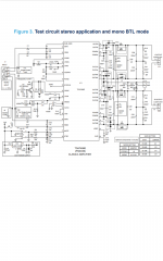
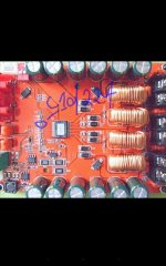
I hope my pins is right, but you can see on the picture if my schematic is righ!
If you can give me some help.
Best regards
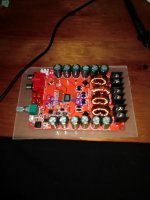
Attachments
Last edited:
Hi,
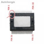
you counted wrong direction i think
you can see a dot mark (punch) on IC
Regards
MANOJ
Thank you for correcting me my dear NANOJ.
I'm using DMM correct? I put the black terminal of DMM on GND terminal of power supply of TDA7498E and red terminal i use to measure the voltage on PINs, is this the right way to measure the PINs?
Sorry to asking you all this stuff, but i don't have to much knowledge on that.
I was trying to count the PINs using the datasheet schematic for the TDA7498E.
I will test the PINs (20, 21, 22 and 29) again and re-enter their values.
Meanwhile, can you Share the values of this PINs for i can compare with the values of my PINs?
Thanks a lot for the help.
Best regards.
Attachments
Last edited:
Hi,
you counted wrong direction i think
you can see a dot mark (punch) on IC
Regards
MANOJ
Hi again my dear NANOJ, i hope you have an nice day.
This time i measure the PINs of my TDA7498E the right way, use your picture as reference and this is the values from the PINs of the IC:
PIN 20 = 0.96v
PIN 21 = 3.15v
PIN 22 = 0.13v and the voltage drop to 0.08v
PIN 29 = 0.00v
I supply the module board TDA7498E with 12v for measure the PINs of the IC.
I don't know what is the problem for this amplifier board TDA7498E don't work.
Can you give me some help?
Big thanks.
Best regards.
I supply the module board TDA7498E with 12v for measure the PINs of the IC.
PIN 20 = 0.96v
PIN 21 = 3.15v
PIN 22 = 0.13v and the voltage drop to 0.08v
PIN 29 = 0.00v
Hi,
PIN 20(STBY) & 21(MUTE) should be minimum 2.5v{pin 21=3.15v is ok} and pin 20=0.96v may be it is taken to High(because 0.5v= low) but PIN 29=0v is low it should be 1.8v.I already said replace 10uF capacitor with new
Regards
MANOJ
Hi my dear NANOJ, i hope you have an nice day.
Can you give me a help?
Is that capacitor i mark on picture i need to replace?
Other question, i measure the outputs speakers from the amplifier and it's reading DC voltage on the outputs. This is the values from the outputs speakers from the amplifier:
Left channel: 1.18v
Right channel: 0.68v
I know this values (DC voltage) from the amplifier in outputs speakers can damage my speakers, right?
I hope you can give me a help.
Many many thanks for your time.
Best regards.
Attachments
- Status
- This old topic is closed. If you want to reopen this topic, contact a moderator using the "Report Post" button.
- Home
- Amplifiers
- Class D
- TDA7498E don't produce any sound (red Amplifier module)