I see no harm in going with at least a 4 layer 2 ounce copper PCB as long as you use the layers effectively to further balance voltage loads of circuit e.g. you could split up left and right channel distribution to help isolate electrical noise and help dissipate heat. Also I think lower impedance coils might possibly improve performance. I'm interested in layered graphene as first contact between copper PCB layers to help with thermal cooling of circuit voltage in copper PCB.
I like the layout of your board so far.
I've never built and audio amplifier before and I appreciate your time and testing to provide good audio amplifier IC module.
Thanks! Would you be willing to pay literally 20 times more for a pcb to have thicker copper and four layers, with no significant benefits to performance, if any at all? The most critical part for heat dissipation is around IC pins where there is very little space, and there is not much we can do about it. Further you get away from IC, trace widths expand exponentially and become less and less of a problem.
I am primarily designing boards for my needs so no need to thank me. If your needs align with mine, you are in luck
")
Last edited:
Totally agreed. I did my own 2-sided pcb-designs based on TPA3118 and TPA3155 that perform similar to TI reference boards. What improvements are to be expected from a 4 layer pcb? Even if THD would drop from lets say 0.003 to 0.001% - hey, this is totally academic as NOBODY on this blue planet will perceive the difference in a double blind test. Imho not worth the money at all.
D
Deleted member 148505
Hi Zdr,
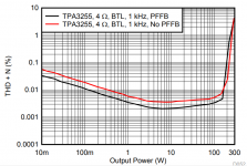
Very nice amp! Congrats. Can you give more details for your distortion measurement? The TI PFFB app note quotes one of the reference conditions of 10Wrms BTL config with a 48v supply with 0.0021% THD. So if your measurement is at 10wrms and you get 0.0016% beats that. It comes down to layout and quality of components. On my amp with PFFB, I managed to get 0.0011% THD for 10wrms.
I think the big SER29X Coilcraft falt copper wire inductors and the layout play a significant role.
TI PFFB app note quotes reference condition as 0.0021% THD+N at 4 ohms load, I think you are mixing up THD and THD+N. On your graph THD+N is 0.0035% at 10W at 10 ohms load.
Nevertheless it is pretty good performance for a soundcard measurement. Even QA401 with "the TPA3255EVM" can't achieve the datasheet's THD+N reference. It is a limitation on the soundcard and QA401's part. For sure you'll get better measurements on AP analyzer.
Attachments
Totally agreed. I did my own 2-sided pcb-designs based on TPA3118 and TPA3155 that perform similar to TI reference boards. What improvements are to be expected from a 4 layer pcb? Even if THD would drop from lets say 0.003 to 0.001% - hey, this is totally academic as NOBODY on this blue planet will perceive the difference in a double blind test. Imho not worth the money at all.
It would be cool just to tinker to push the limits of technology and not settle for the status quo.
In retrospect of discussion i seriously think 1 layer of graphene with a layer of copper could possibly work fantastic. The overall PCB dimensions could possibly be smaller to save materials and still offer a better overall electrical operation and dissipate heat better and offer better audio quality.
I'd pay $249 for such TPA3255 design.
20x..... No way.
Last edited:
If you want to tinker ...
What is your goal?
Focusing on THD: Have a look at the THD measurements TI did with various inductors and you will find the dominating contribution in the inductors.
If you want to push K2 to the limits, design a PCB with perfect symmetrical magnetic loops. I think there is some room remaining for improvement compared to the TI RefBoard.
But there may may other goals to tinker besides THD as well...
Btw, what specific properties of graphene let you expect improvements?
Last edited:
bucks money
Why? Graphene is much better electrical conductor than copper and much better at dissipating heat. Graphene is superconductor electrically and has much better heat dissipation behavior.
Hybrid application for electronic PCB and other electrical conductors where Graphene can be applied effectively have great potential to help improve electrical design of electronic components for machines from computers to sewage pump motor drivers.
It's not new technology but emerging technology.
I'd pay $249 for such TPA3255 design.
20x..... No way.
I am selling my boards for 5eur, you do the math
What improvement do you expect from a perfect conducting pcb? We are talking about class-d-amps based on TPA325x with Rdson >50mR, real copper winding inductors etc.bucks money
Why? Graphene is much better electrical conductor than copper and much better at dissipating heat. Graphene is superconductor electrically and has much better heat dissipation behavior.
Hybrid application for electronic PCB and other electrical conductors where Graphene can be applied effectively have great potential to help improve electrical design of electronic components for machines from computers to sewage pump motor drivers.
It's not new technology but emerging technology.
Heat conductivity maybe a more interesting feature to spread dissipation along the hole pcb.
D
Deleted member 148505
Listening test against MF XA50 clones, with Wifi Amp A/B switching module.
TPA is wins this round, next one is going to be a real challenge: RMI-FC100
View attachment 892246
Hi zdr,
That about listening test between RMI-FC100 and yours TPA3255 implementation ?
You'd get more benefits by convincing an auto manufacturer to use SiC-reinforced aluminum connecting rods in their engines than by trying to shoehorn graphene into some PCB that DOES NOT NEED IT.It would be cool just to tinker to push the limits of technology and not settle for the status quo.
In retrospect of discussion i seriously think 1 layer of graphene with a layer of copper could possibly work fantastic. The overall PCB dimensions could possibly be smaller to save materials and still offer a better overall electrical operation and dissipate heat better and offer better audio quality.
I'd pay $249 for such TPA3255 design.
20x..... No way.
Hi zdr,
That about listening test between RMI-FC100 and yours TPA3255 implementation ?
I am currently working on putting TPA3255 in a box first.


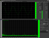
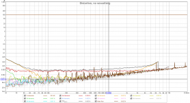
Nailed the ground loop by merging two ground planes with thick copper bars. Now I have cumulative distortion from XR+DAC, PGA Pre and TPA3255 at 0.0035%, still with MLCCs in the signal path, uncalibrated, running off of a single 20V PS. It can only go lower from here.
Attachments
Almost done, CLIP and FAULT notification integrated with PGA Pre.
Pga Pre with TPA3255 power amp in class D - YouTube

Pga Pre with TPA3255 power amp in class D - YouTube
- Home
- Amplifiers
- Class D
- Compact TPA3255 design with PFFB and single PS