Im pretty new to understanding them fully but i have a basic enough understanding so heres the dilemma,
The amp works flawlessly with a direct AC current from the wall, But i want to power it via li-ion battery's, however i always want to limit its current voltage to 8.6vs as the volume etc is fine with this for what it is being used for and here in is where the problems arise!
When i use a boost converter, the moment you go over a certain volume the amp will just keep cutting out and coming back, i know this is all to do with voltage drop and possibly an ampage issue which is fine as i dont need it to go to the volumes its hitting when this happens so onto what i want to do.
I thought about how i would go about using a POT to control the max volume, thats fine if i didn't want to also control the max volume via this POT as this now means i could end up going over the max volume so i thought why not just adjust the gain? and this is where im hitting a wall, ive not the first idea which parts i need to replace on the pam board to adjust the gain so it doesn't go so loud, i thought about adding a couple of POTs onto the board to be able to adjust the gain but im unsure where i would put them...
Thoughts? Advice on this one and how i would go about doing it?
TLDR - i want to adjust the gain but need to know how
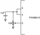
Pin 5, "Volume Control", on PAM8610 is an input where the gain can be controlled. Reference in the datasheet ( https://www.diodes.com/assets/Datasheets/PAM8610.pdf ) to a "Table 1" which I can't find. Figure 21 in the datasheet gives a hint.
Awesome, i must of overlooked that, upon looking into it i can indeed locate the pin no problem, would i be right in thinking that changing the resistor/capacitor on the board would adjust the gain?
I do not find the datasheet very clear on the gain-adjustment.
My impression from what I have found around is that you can connect it as shown below and adjust the gain on the 10K potentiometer (trim-pot).
The capacitor is just for decoupling.
Attachments
Yes that was the problem I was having, unable to see exactly what I would adjust, I've bought a few extra more as they are so cheap and intend on experimenting! When looking at the schematic I've an idea what I will attempt to replace, if you was testing away what would you change?
Yes that was the problem I was having, unable to see exactly what I would adjust, I've bought a few extra more as they are so cheap and intend on experimenting! When looking at the schematic I've an idea what I will attempt to replace, if you was testing away what would you change?
With a small module, there are limits to how much you can reasonably change. The space available on a small board is limited. Audio-wise foil capacitors are better (linearity) than SMD ceramic capacitors but most likely you do not have space for replacement. What I would find important is a good 2200uF power line decoupling capacitor close to the power terminals of the board. Small SMD boards are often short of power line decoupling which is bulky.
Oh I already thought about doing that but it unfortunately doesnt fix my problem XD hench why I thought I'd go down the route of changing the cap that determines the gain, I want to decrease its gain so its matter of finding which caps do it, then replacing them to reduce it 
Oh I already thought about doing that but it unfortunately doesnt fix my problem XD hench why I thought I'd go down the route of changing the cap that determines the gain, I want to decrease its gain so its matter of finding which caps do it, then replacing them to reduce it
If the gain is voltage-controlled on pin 5, I see no capacitor that changes the gain.
- Status
- This old topic is closed. If you want to reopen this topic, contact a moderator using the "Report Post" button.
- Home
- Amplifiers
- Class D
- Adjusting Gain on PAM8610 amp