I have started my first project, a 3e audio TPA3255 with a douk 400w 48v smps and some bits from audiophonics.fr. The problem I have is doukmall on eBay sent me a the 24v version of the power supply and are being d*cks about correcting their mistake. I’m in the Uk and need to find a cheap compact 48v smps or something like a TPA3251 in Europe to get my project back on track quickly. Any ideas? Thanks in advance.
Get in touch w Cresnet, he sells very good and silent power supply.
BR,
Eric
Hi,
If you want to get the best of your TPA3255, I will get a Linear PSU.
I made mine for less than $80
Find a Toroidal 30V / 200 or 250 VA (30 V AC will give you about 46 V DC)
A AC / DC caps convertor with Audiophile grade capacitors Like this :
Send me a private message if you need help

Thanks for both those replies. After 4 days of emails doukmall has agreed to send the correct smps out which is what I wanted. I will try the linear option if the smps does not sound very good. I don’t need the full power of the TPA3255 but my speakers are 8ohms so I didn’t go for the TPA3251.
Thanks for both those replies. After 4 days of emails doukmall has agreed to send the correct smps out which is what I wanted. I will try the linear option if the smps does not sound very good. I don’t need the full power of the TPA3255 but my speakers are 8ohms so I didn’t go for the TPA3251.
I own both, TPA3255 + 3251, they drive my 8 ohms high floor speakers perfectly well. Look at this thread :
TPA3251d2
Still waiting for my 48v smps but thought I would use the 24v in the mean time. I have just finished building my first amp but I have a few problems.
1) It’s not very loud. I thought I would get about 70w with the 24v 400w smps
2) My cheap soldering iron came with solder. All my joints are grey and not shiny.
3) My hook-up wire was too thick and not flexible (I can solve this one).
4) I used a SMD type potentiometer 10k and at min vol there is sound coming through. I was testing it with a 1v input from an iPhone 5S. At max vol it is not that loud (I couldn’t upset the neighbours). Could I have wired it wrong? I could only go off what was on the Audiophonics website, it cost 16euros.
It sounds as good as my Onkyo, maybe a touch better. I had to turn up the smps to it max before the amp would operate. I am quite pleased with it so far. I thought it would blowup when it first turned it on.
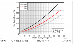
If your 3255 is connected as BTL output, the amplifier output power from a 24vdc power supply with a 8ohm load is about 30W, see graph attached, grey curve. To get about 75W you need a 36Vdc supply. With your 48Vdc supply you will get roughly 125W/channel into 8 ohm loads.
Attachments
Last edited:
Hi,
the soldering iron might not get hot enough or the solder (like most in kit´s) is bad quality and lead free.
Get a reel of good solder with "Pb" (lead) content like Pb37 or Pb40 for your hobby. Usually 0.8-1mm is fine. STANNOL, FELDER, Weller are good quality.
You can use solder with lead content on anything you do, but not so well the other way round. It is considered a bad idea to repair older lead soldered components with lead free solder.
The lead free stuff melts at much higher temperature and is harder than old style solder with lead contend. The fuzz about lead-free is only for production. For private use and repairs leaded solder is still allowed.
Might change in the future or be different outside EU.
A potentiometer has 3 legs, so you can wire it wrong, no problem.
Put the wiper in the middle position and measure the resistance. Usually the legs with the nominal value (10k) are 1 and 3. They go to ground and source. The variable leg (No. 2) is connected to the amp input. This way the source (pre amp, CD, etc) sees 10k all the time.
The input of the amp can be dialed to any percentage of the input voltage. If you turn it to ground, you have no voltage at all, on the other end of the scale you have 100%. This is for linear pots.
Logarithmic gets more complicated, here you can get 1 and 3 wrong, too. Connected right you can turn louder evenly. If the volume jumps or does not really change while turning, you got 1 and 3 wrong.
Thanks Turbo. I think you are right that the solder is lead free. The potentiometer is from Audiophonics.fr ‘Potentiometer switched Stereo anti pop - Resistors 1% SMD 10k LOG’. It seems to work perfectly except for at minimum volume I can still hear the music faintly. Could this be normal for this potentiometer? I wired the potentiometer ground to the amp source - and and also to the rca socket -. My amp only has a single stereo input.
Not sure when I will get the case for my amp with this Coronavirus crisis. I got hold of some hookup wire and re-wired the amp. I’m still not please with the potentiometer, there are some very good smd type ones out there but at least mine sound ok. I was struggling to solder to the RCA sockets and speaker terminals even with new lead solder, I need some practice.
Can I insert pictures from my phone on this forum?
Can I insert pictures from my phone on this forum?
The pot´s connections are pictured at the shops page. It is no "Pot", but a switched resistor with 21 positions. If you have wired it as shown (in=3, out=2, ground=1) it might be normal to have some minor signal in the last switching position. Maybe check again?
It is a good idea to ground such a pot´s case if it is not screwed to a grounded metal case. This way you prevent it from humming when you touch it.
It is a good idea to ground such a pot´s case if it is not screwed to a grounded metal case. This way you prevent it from humming when you touch it.
I have wired it correctly, checked yesterday when I re-wired the amp. I don’t have a case but I mounted everything to a length of aluminium bent up at each end, it is like a case without sides and top. There is no humming coming from the amp when touched or during use. The amp is very sensitive and I only have one source clean enough to play my music. I have ordered an iBasso DX160 to use as source. I could have got a DAC instead but the DX160 will do so much more as it can stream, store, be a usb DAC and it is portable.
My iBasso DX160 arrived today �� It sounds awesome, the detail, clarity and its really clean with no distortion. Both streaming through the DAP and when in USB DAC mode it sounds perfect. I can’t wait to get my 48v smps, but I am impressed with what 24v can do. I only have a pair of Mordaunt Short Aviano 1 speakers so they won’t take that much more power. I found out the wire I used was 2T (I think) spec which has a high tin content used on aircraft, not pure copper or silver so that will upset all the audiophiles out there. When I get a better switched resistor or pot I might stick some copper wire in there. My soldering is not the greatest yet so I might get some help from a pro for the next re-wire. I should post some pics (if I can work out how). I’m working my way through the Amazon Music new music playlist atm so I will get back to that.
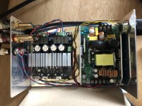
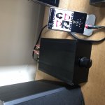
I hope this image uploads. The aluminium that I have mounted everything in represents the case I am waiting for and measures 145x200x82mm. I don’t like the gland for the power lead and will work out something else for the proper case. I did not install the power switch or the additional panel mounted fuse in this build. I plan to put a wooden front on the proper case, something like Zebrano with some laser etching.
Attachments
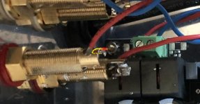
Suggestion; Reroute your black/yellow wires connected from your volume to the amplifier input, they are passing right above AC mains and are not shielded. You have a better chance of having a less noisy amp if these black/yellow are moved away from mains. Just moved them on the other side of your power supply.
BR
Eric
BR
Eric
Or, cannibalize an old stereo cable with RCA's -- you probably have one lying around somewhere, forgotten about when one of the connectors became intermittent -- makes excellent shielded interconnect.
As long as you have the input connectors on the opposite end from the volume control, then another nearly chassis-length run back to the amp inputs, it really should be shielded. Even if you didn't have a switching power supply in the same box, shielded would be considered 'standard practice'.
As to your 'soldering skill' -- how big is your iron? Those are some honking-serious output jacks and they'll take a lot of heat. A better bet would be a 100 Watt gun. Otherwise, there's only one place you can solder a stranded 16 gauge tinned-copper wire to it: Right at the end of the hole where the brass is thinnest. Make a sharp hook in the wire, hook it in that hole, and put a slight bit of tension on it with a paperweight or hand tool. Then make firm contact with the iron on that spot to transfer heat before feeding in the solder.
It may not be 'your skill' at all.")
Cheers
As long as you have the input connectors on the opposite end from the volume control, then another nearly chassis-length run back to the amp inputs, it really should be shielded. Even if you didn't have a switching power supply in the same box, shielded would be considered 'standard practice'.
As to your 'soldering skill' -- how big is your iron? Those are some honking-serious output jacks and they'll take a lot of heat. A better bet would be a 100 Watt gun. Otherwise, there's only one place you can solder a stranded 16 gauge tinned-copper wire to it: Right at the end of the hole where the brass is thinnest. Make a sharp hook in the wire, hook it in that hole, and put a slight bit of tension on it with a paperweight or hand tool. Then make firm contact with the iron on that spot to transfer heat before feeding in the solder.
It may not be 'your skill' at all.
Cheers
Attachments
All suggestions have been noted. I think the yellow and black wires are a tiny bit too short to be routed the other way round the power supply but I will try. Is shielded wire with the braided wire on the outside and doesn’t the shielding need to be grounded to work? All the cable runs are very short, I think that helps to stop interference. When I move the amp to its proper case I can change the routing slightly and will need to re-wire the speaker terminals ( solder where the metal is thinnest (great tip thanks )). I haven’t noticed any interference but will try to route those wires differently. Thanks for the advice Fortier and Rick.
Finished (almost)
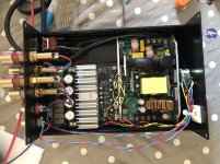
My case arrived finally! It was just big enough, I would get a slightly bigger one next time. Had an issue with one channel being almost silent and after some investigation a bit of swarf was shorting a rca socket. I’m still waiting for the 48v smps. Sound quality is excellent. I could hear some hissing when I was listening to a hi-res fleetwood mac album but then put on some newer hi-res music on it was totally his free. If the case was 1mm smaller I would have had problems. As it was I could not fit the power switch so the amp would be standing vertical. I am happy with the final result.
My case arrived finally! It was just big enough, I would get a slightly bigger one next time. Had an issue with one channel being almost silent and after some investigation a bit of swarf was shorting a rca socket. I’m still waiting for the 48v smps. Sound quality is excellent. I could hear some hissing when I was listening to a hi-res fleetwood mac album but then put on some newer hi-res music on it was totally his free. If the case was 1mm smaller I would have had problems. As it was I could not fit the power switch so the amp would be standing vertical. I am happy with the final result.
Attachments

- Status
- This old topic is closed. If you want to reopen this topic, contact a moderator using the "Report Post" button.
- Home
- Amplifiers
- Class D
- Ideas/advice TPA3255 project