Hi,
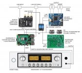
I'm trying to collect the info for the new project - the integrated amp with USB DAC, Power Amp and Headphone Amp. Found this thread among many other Class D threads and finally read through all posts. Here are some questions.
I need USB input in the amp. Can I connect directly the USB DAC (https://www.amazon.com/gp/product/B07KN6P9QB) output to the input of the analog version of the MA12070? In my previous amp project I used pre-amp between DAC and power amp. It also served for volume control. How do you control the volume in MA12070? Do you need to use any external controller (e.g. Arduino, Raspberry Pi Zero) and control volume through I2C?
I'm not sure how to switch DAC output from Power Amp (MA12070) to the Headphone Amp (not decided yet what to use for it). Should I use relay controlled by the same Arduino or Pi?
Thanks in advance!
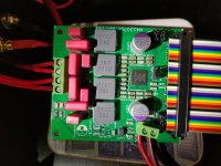
I designed a very simple PCB for the ma12070p chip. It's a copy of the reference design, with the following changes:
When I first powered it up, it didn't work. I was worried there was a solder bridge on the ma12070p chip, as those are really tiny pins. But the problem was actually with what should have been the simplest part of soldering the board: the SMD 40-pin header. The first problem was the part I got was not a perfect match for the PCB footprint. The pins lined up properly, but they are longer than the pads. That shouldn't have been a big deal, but the pin header got mis-aligned during my poor man's "reflow" process (using a frying pan). In short, some pins simply weren't connected. Un-soldering that pin header was a major pain, and I actually destroyed one of the solder pads in the process (fortunately, it was a no-connect pad). Ironically, the 40-pin header was also the second most expensive part (the actual ma12070p being the most expensive). In a subsequent revision of this board, I think I'll just use a through-hole pin header to save myself the grief.
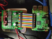
Anyway, once I got that header re-soldered correctly, it worked! It's been playing fine while I took pictures and typed up this message.
I have a few extra PCBs, if anyone wants one, let me know via PM (no charge, just cover shipping). I'm also happy to post the Gerbers, schematic, KiCad files, and BOM if there's any interest.
- Has a 40-pin header, for easy pairing with a Raspberry Pi
- Jumper to select 5v from on-board buck converter or from the 40-pin header (e.g. can omit populating the buck converter circuit and use the RPI's 5v supply)
- Jumpers to select I2C address
- Jumper to either supply MCLK explicitly (e.g. from Allo Kali, though I couldn't get this to work with the reference board), or to tie MCLK to BCLK
- Uses the recommended circuit for speaker cables over 60mm in length (e.g. actual LC circuit)
When I first powered it up, it didn't work. I was worried there was a solder bridge on the ma12070p chip, as those are really tiny pins. But the problem was actually with what should have been the simplest part of soldering the board: the SMD 40-pin header. The first problem was the part I got was not a perfect match for the PCB footprint. The pins lined up properly, but they are longer than the pads. That shouldn't have been a big deal, but the pin header got mis-aligned during my poor man's "reflow" process (using a frying pan). In short, some pins simply weren't connected. Un-soldering that pin header was a major pain, and I actually destroyed one of the solder pads in the process (fortunately, it was a no-connect pad). Ironically, the 40-pin header was also the second most expensive part (the actual ma12070p being the most expensive). In a subsequent revision of this board, I think I'll just use a through-hole pin header to save myself the grief.
Anyway, once I got that header re-soldered correctly, it worked! It's been playing fine while I took pictures and typed up this message.
I have a few extra PCBs, if anyone wants one, let me know via PM (no charge, just cover shipping). I'm also happy to post the Gerbers, schematic, KiCad files, and BOM if there's any interest.
Attachments
I designed a very simple PCB for the ma12070p chip. It's a copy of the reference design, with the following changes:
- Has a 40-pin header, for easy pairing with a Raspberry Pi
- Jumper to select 5v from on-board buck converter or from the 40-pin header (e.g. can omit populating the buck converter circuit and use the RPI's 5v supply)
- Jumpers to select I2C address
- Jumper to either supply MCLK explicitly (e.g. from Allo Kali, though I couldn't get this to work with the reference board), or to tie MCLK to BCLK
- Uses the recommended circuit for speaker cables over 60mm in length (e.g. actual LC circuit)
When I first powered it up, it didn't work. I was worried there was a solder bridge on the ma12070p chip, as those are really tiny pins. But the problem was actually with what should have been the simplest part of soldering the board: the SMD 40-pin header. The first problem was the part I got was not a perfect match for the PCB footprint. The pins lined up properly, but they are longer than the pads. That shouldn't have been a big deal, but the pin header got mis-aligned during my poor man's "reflow" process (using a frying pan). In short, some pins simply weren't connected. Un-soldering that pin header was a major pain, and I actually destroyed one of the solder pads in the process (fortunately, it was a no-connect pad). Ironically, the 40-pin header was also the second most expensive part (the actual ma12070p being the most expensive). In a subsequent revision of this board, I think I'll just use a through-hole pin header to save myself the grief.
Anyway, once I got that header re-soldered correctly, it worked! It's been playing fine while I took pictures and typed up this message.
I have a few extra PCBs, if anyone wants one, let me know via PM (no charge, just cover shipping). I'm also happy to post the Gerbers, schematic, KiCad files, and BOM if there's any interest.
Great job! It's a little too blurry to see...can you point me to the 5V buck converter you used?
Mike
Great job! It's a little too blurry to see...can you point me to the 5V buck converter you used?
The design uses the exact same buck converter as the reference PCB, the Texas Instruments TPS62175DQCT. It's a tiny IC, and the pins might be even smaller than those of the ma12070p. In the build of my board (pictured above), I didn't even populate the buck converter circuit (the "blurry" to which you refer might just be the empty pads!); I'm getting 5v from the RPI. I originally planned to populate the buck converter circuit, just to validate that it works, but Mouser was out of stock on the TPS62175DQCT when I placed my parts order.
The design uses the exact same buck converter as the reference PCB, the Texas Instruments TPS62175DQCT. It's a tiny IC, and the pins might be even smaller than those of the ma12070p. In the build of my board (pictured above), I didn't even populate the buck converter circuit (the "blurry" to which you refer might just be the empty pads!); I'm getting 5v from the RPI. I originally planned to populate the buck converter circuit, just to validate that it works, but Mouser was out of stock on the TPS62175DQCT when I placed my parts order.
Sorry...was referring to the black DC to DC converter, but after googling I came up with TOBSUN EA15-5V maybe??? Looks like you are powering the amp directly from the linear power supply and also feeding this from the PS, then 5V to the Pi.
Sorry...was referring to the black DC to DC converter, but after googling I came up with TOBSUN EA15-5V maybe??? Looks like you are powering the amp directly from the linear power supply and also feeding this from the PS, then 5V to the Pi.
Ha! That's just a cheap step-down converter I found on Amazon, EPBOWPT Power Converter Regulator DC 12V 24V to 5V 5A 25W Regulated Power Supply Step Down Module. It seems there are countless X-to-5V buck/step-down converters available. I wanted one that was regulated and had plenty of current capability for the RPI, was completely enclosed, and had nice, easy-to-use input/output terminals. This one ticked all those boxes.
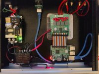
The main 24v supply isn't linear, it's a switch-mode, a Meanwell EPP-200-24. But yes, the 24v output goes both to the 5v buck converter, and also directly to the ma12070p board. And as you said, the 5v supply from the step-down converter goes to the RPI.
Congrats! Nice amps. Here are some mine amps. I developed 3D printed stands so there is a bunch of four amps MA12070P, two ones in BTL mode and another ones in PBTL modeI have a few extra PCBs, if anyone wants one, let me know via PM (no charge, just cover shipping). I'm also happy to post the Gerbers, schematic, KiCad files, and BOM if there's any interest.
Attachments
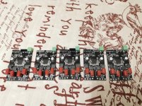
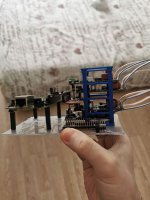
Congrats! Nice amps. Here are some mine amps. I developed 3D printed stands so there is a bunch of four amps MA12070P, two ones in BTL mode and another ones in PBTL mode
That's awesome! Two questions:
- Do all four amps share the same I2S source? If so, how do you "multiplex" the I2S? And similarly, for PBTL, what does the ma12070p expect in terms of the I2S stream? I.e. does it expect only one channel's info in the I2S stream (i.e.a mono I2S stream), or does it expect two channels (typical I2S stream) and simply ignore one channel?
- Did you copy the PVDD input circuit from the reference board? In particular, RPVDD, the 0.1R that is in series with the V+ input? It's shown on the schematic for the reference board, but it's not listed in the BOM. In my design, I just made room for a typical 1206 SMD resistor. But, in theory, there could be fairly high current going through that resistor, so it seems like it should be rated for quite-high wattage (eight amps at 26V would be over 200 watts). Resistors rated with this kind of wattage are neither small nor cheap, so I'm sure the reference board uses something much more modest (clearly bigger than 1206 though). When I assembled the board, I just used a piece of wire lead, so it's essentially 0R.
1. There is DSP as a middle I2S chain link. It separates stereo from Beaglebone Black into mids, highs and lows. Since ma12070p use in PBTL only left channel, I modified that output in sigma studio. My adau1452 DSP has 4 i2s outputs, so two ones in stereo, third left output channel connected to the left input channel (filtered through crossover), fourth output left channel connected to the right input channel (filtered through crossover).
2. Yes, I found 1W 0.1R resistor on lcsc, it was the biggest one smd that I found on the store.
2. Yes, I found 1W 0.1R resistor on lcsc, it was the biggest one smd that I found on the store.
Attachments
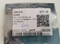
You can find some 1-3W resistors. I found one similar to the one placed on the reference board Viking Tech|Viking Tech CS25FTER100|Low Resistors & Current Sense Resistors - Surface Mount|LCSC
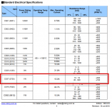
But actually I have no reasons to put more than 1W resistor because as you can see there is 10A limit for that 1W resistor. Based on table 7-1 of datasheet max output current is 8A for this amp and I believe there will be over-current protection if the output current exceedes that value.
But actually I have no reasons to put more than 1W resistor because as you can see there is 10A limit for that 1W resistor. Based on table 7-1 of datasheet max output current is 8A for this amp and I believe there will be over-current protection if the output current exceedes that value.
Attachments
Last edited:
I don't understand how that datasheet can list the resistor's power rating, and also a max fixed current, as power is a function of both voltage (drop) and current.
At 0.1 ohms, the voltage drop across RPVDD at 8 amps is: V=IR = 8*0.1 = 0.8V.
Power is P = V*I, so we have P = 0.8*8 = 6.4 watts. So I think RPVDD should have a power rating of at least 6.4 watts.
I picked a random power resistor, and it's datasheet seems to be consistent with my math. Bourns CRA2512. This is a 3W part, and the datasheet lists maximum current not as a fixed value, but as a function of current and resistance: max I = sqrt(P/R). So in the 3W-rated case, for a 0.1R, that's a max current of about 5.5 Amps.
In reality, I doubt anyone is going to push the full 8 amps through these chips for typical music playback, so I'm probably over-thinking this. But if you wanted to design a board capable of testing the extremes of the chip, I think a higher power resistor is needed.
Hi,
What should be the output of the power supply for MA12070? Lets' say I use 24V then what should be the current? 2A, 4A, 6A, 8A, 10A?. I can use the high current power supply but the most models look too bulky for the enclosure which I'm going to use. Should it be defined by the output wattage which I'm going to use? So if I will use 20W output max should I just use 2A max power supply (1A per channel)?
Thanks!
What should be the output of the power supply for MA12070? Lets' say I use 24V then what should be the current? 2A, 4A, 6A, 8A, 10A?. I can use the high current power supply but the most models look too bulky for the enclosure which I'm going to use. Should it be defined by the output wattage which I'm going to use? So if I will use 20W output max should I just use 2A max power supply (1A per channel)?
Per the ma12070(p) datasheet, the max current for the amp IC itself is 8 amps. So ideally, you'd use a power supply capable of supplying at least eight amps.
That said, in typical music playback roles, it's unlikely that the chip will actually draw that much current, certainly not for any length of time.
And in your particular case, you know you won't push the chip anywhere near its limit. However, the potential problem with using an undersized power supply is that you have to think about what happens if the chip does try to exceed the supply's current rating? Good quality power supplies have well-defined behavior when their ratings are exceeded. But the cheap/no-name stuff can be a potential source of risk in that scenario. At a minimum, I'd suggest an appropriately-rated mains fuse that will disconnect power from your amp if the current draw is too high.
So, if you know you'll never go above 20watts total, then at 24v, you need a 20W/24V = 0.83A capable power supply.
How small do you need this PSU to be? If you go back to the previous page, you can see a picture of my ma12070p amp. I'm using a Meanwell EPP-200-24 power supply. It's pretty small, and rated for 200W (just over 8 amps).
You're right, since I didn't test it at max level (actually 50% is pretty much comfortable max for my 4Om speakers. But for sure, for the max 26-27V power supply and 8Om speakers it's better to use 3W at least. Good advice!At 0.1 ohms, the voltage drop across RPVDD at 8 amps is: V=IR = 8*0.1 = 0.8V.
Power is P = V*I, so we have P = 0.8*8 = 6.4 watts. So I think RPVDD should have a power rating of at least 6.4 watts.
In reality, I doubt anyone is going to push the full 8 amps through these chips for typical music playback, so I'm probably over-thinking this. But if you wanted to design a board capable of testing the extremes of the chip, I think a higher power resistor is needed.
...How small do you need this PSU to be? If you go back to the previous page, you can see a picture of my ma12070p amp. I'm using a Meanwell EPP-200-24 power supply. It's pretty small, and rated for 200W (just over 8 amps).
matt_garman, thank you for the PS info. It's probably more than I need power and price wise
") But I think it's impossible to find any smaller PS with such spec. It's even smaller than PS which I was going to use with a lower wattage:
But I think it's impossible to find any smaller PS with such spec. It's even smaller than PS which I was going to use with a lower wattage:Mean Well LRS 100w 24V 4.5A Switching Power Supply | eBay
The other way to restrict the current through the chip is to limit the maximum volume level through I2C. For example if 256 (I don't know the real number yet) is the max volume level in the chip then limiting the value to 128 will ensure that it will never consume more than 4A.
Last edited:
Hi folks. Can you please explain how you was able to connect these boards from aliexpress via i2c? I'm trying to follow pinout of SDA/SCL but I'm not able to detect it on the 0x20 address on a raspberry pi i2c port. I've also tested a port on raspberry with other i2c devices as well and seems it's working. Very strange thing which makes me nervous that I do see i2c slave (ma12070p board) is actually have SDA/SCL pins pulled up and I'm not sure is that okay or not.
Thanks Onefabis. Looks like I did everything correctly. EN/MUTE is actually pulled down and UP accordingly by the board itself. The thing is that looks like i2c bus at merus board is using 5v and rpi is using 3.3v. I'm pulling it down by 1k resistor but looks like it not enough...
- Home
- Amplifiers
- Class D
- Infineon MA12070 Class D