Dear diy'ers,
after reading through many many threads, it is time for me to ask a question of my own. I've worked with discrete AB, AB Chipamps and integrated Class-D before and have used them in many project so far. But currently I am running circles with an implementation of the IRS2092 in combination with the IRFI4019.
Upfront: Intended purpose of this amp and source of parts
I am not making a secret out of it, that the PCB I layed out for the amp is meant to be a replacement for a burned out discrete AB Amp used in an old JBL subwoofer. This project is part of my electronics hobby ambitions, so please keep that in mind, that I did not spend a full-blown development cycle with multiple revisions over the PCB or parts of the schematic (may be that is even the fault already).
All parts are sourced from accountable sources, with some exceptions, everything came from mouser. This also applies to the IRS2092 and IRFI4019, so I take any problems with counterfeit-parts out of the equation.
Environmental Conditions:
The Amp will be powered with a 2x32V transformer, which translates to roughly +- 45V supply voltage after rectification. Supply Caps consist of two times 4700µF (one per rail).
Please note: CSD is not connected to anything but a cap, all UVP, OVP and OTP circuits are not connected in this state.
As reference the IRAUDAMP7d and IRAUDAMP7s were used. The Chip in use is in the SOIC16 package and soldered to a DIP to SOIC16 adaptor for easy parts change and testing.
All tests were done currently with the input tied to GND.
The speaker output is protected by a UPC1237 circuit.
Equipment at Hand:
For testing I have several multimeters, transformers and an old RFT EO213 analog scope.
The problem:
It seems that the AMP is not starting or not properly. I was not able to notice any switching output before/after the inductor or on the LO and HO outputs of the IRS2092. Apart of this, the output (aka. VS) is roaming around 1,5V in this state, which causes a speaker DC protection to trip.
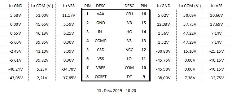
Measuring CSD against VSS shows around 3,09V which brings me to the conclusion that I am even below Vth2 (Which is (|Vaa| + |Vss|)*0,3 = 11,2V*0,3 = 3,36V) and far away from Vth1 (Which would be 7,84V).
CSD seems not to jump around between Vth1 and Vth2, which gives me the impression that it is not trying to properly go through a cycle of let's say an OCP event either triggert by the setting of OCSET or CSH.
I've already changed the IRS2092 just to make sure, but without any changes to the current behavior of the amp. All supply voltages seem to be in spec, as far as I can tell. Vaa and Vss are being generated from V+ and V- by a Resistor+Zener combination and are about +-5,6V. VCC is generated via TIP41C+Zener and measures around 15V to COM (V-).
Honestly I am a bit puzzled currently and would appreciate some hints and may be even someone who shows me the obvious mistake I must have made and which I seem to blind to see :/
Measurement, Schematics and Layout:
Measurements of IRS2092
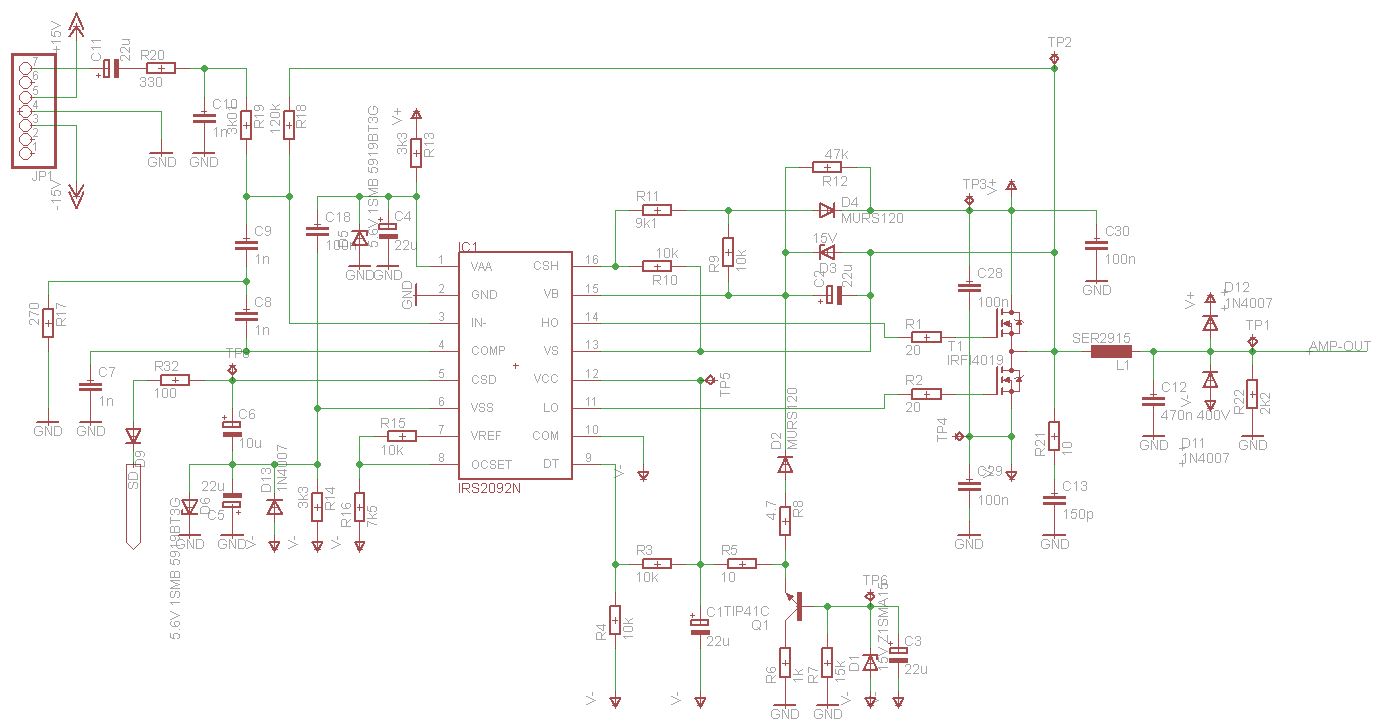
Schematic of the AMP part
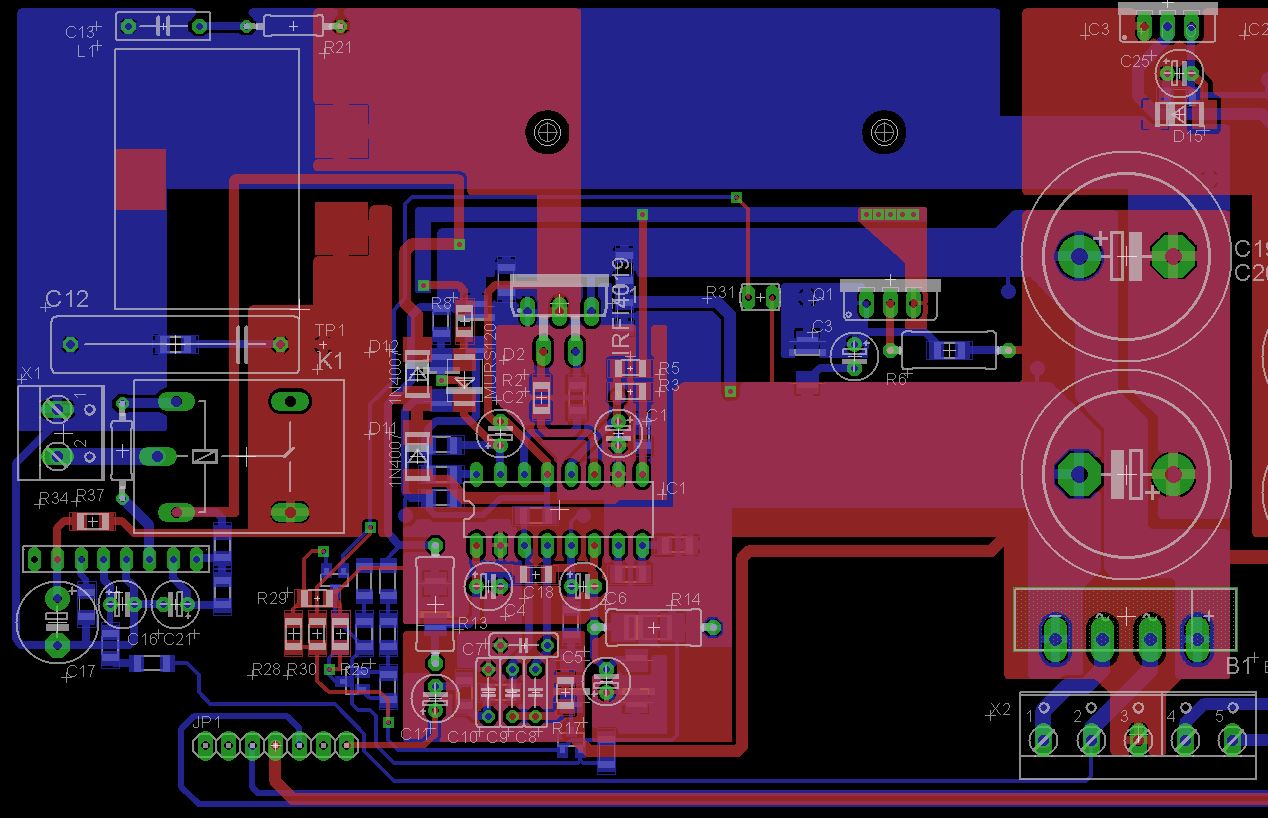
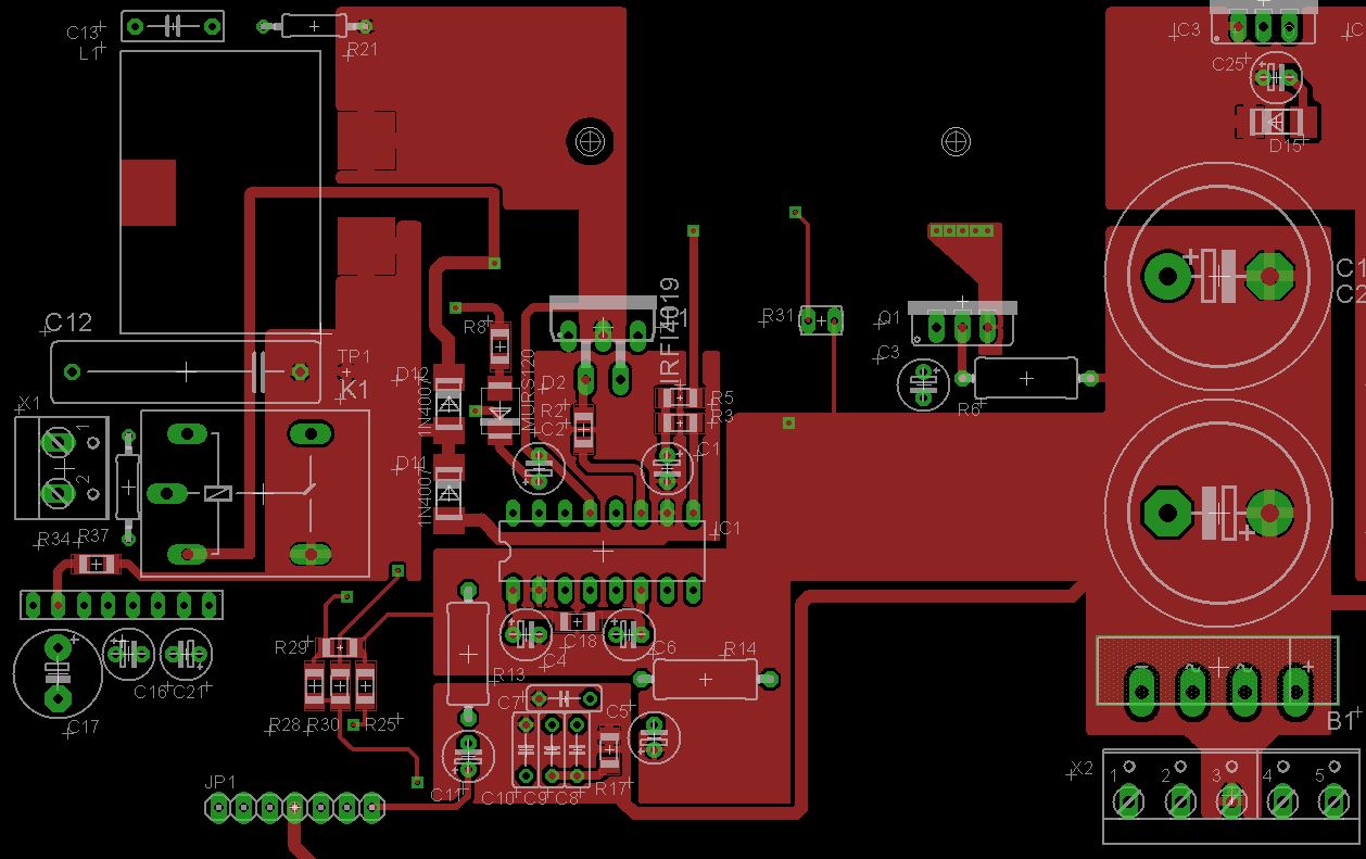
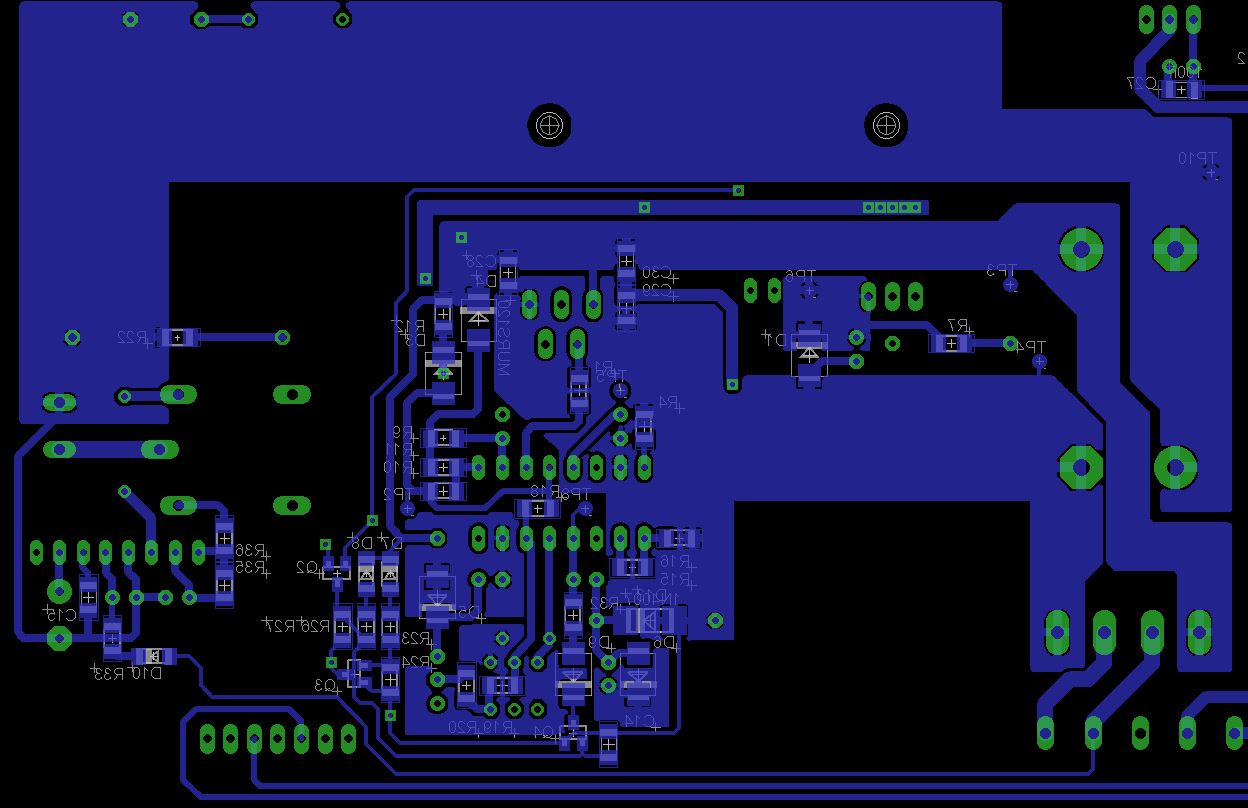
Layout with both, top(red) and bottom(blue) layer.
All help is really appreciated, many thanks upfront!
after reading through many many threads, it is time for me to ask a question of my own. I've worked with discrete AB, AB Chipamps and integrated Class-D before and have used them in many project so far. But currently I am running circles with an implementation of the IRS2092 in combination with the IRFI4019.
Upfront: Intended purpose of this amp and source of parts
I am not making a secret out of it, that the PCB I layed out for the amp is meant to be a replacement for a burned out discrete AB Amp used in an old JBL subwoofer. This project is part of my electronics hobby ambitions, so please keep that in mind, that I did not spend a full-blown development cycle with multiple revisions over the PCB or parts of the schematic (may be that is even the fault already).
All parts are sourced from accountable sources, with some exceptions, everything came from mouser. This also applies to the IRS2092 and IRFI4019, so I take any problems with counterfeit-parts out of the equation.
Environmental Conditions:
The Amp will be powered with a 2x32V transformer, which translates to roughly +- 45V supply voltage after rectification. Supply Caps consist of two times 4700µF (one per rail).
Please note: CSD is not connected to anything but a cap, all UVP, OVP and OTP circuits are not connected in this state.
As reference the IRAUDAMP7d and IRAUDAMP7s were used. The Chip in use is in the SOIC16 package and soldered to a DIP to SOIC16 adaptor for easy parts change and testing.
All tests were done currently with the input tied to GND.
The speaker output is protected by a UPC1237 circuit.
Equipment at Hand:
For testing I have several multimeters, transformers and an old RFT EO213 analog scope.
The problem:
It seems that the AMP is not starting or not properly. I was not able to notice any switching output before/after the inductor or on the LO and HO outputs of the IRS2092. Apart of this, the output (aka. VS) is roaming around 1,5V in this state, which causes a speaker DC protection to trip.
Measuring CSD against VSS shows around 3,09V which brings me to the conclusion that I am even below Vth2 (Which is (|Vaa| + |Vss|)*0,3 = 11,2V*0,3 = 3,36V) and far away from Vth1 (Which would be 7,84V).
CSD seems not to jump around between Vth1 and Vth2, which gives me the impression that it is not trying to properly go through a cycle of let's say an OCP event either triggert by the setting of OCSET or CSH.
I've already changed the IRS2092 just to make sure, but without any changes to the current behavior of the amp. All supply voltages seem to be in spec, as far as I can tell. Vaa and Vss are being generated from V+ and V- by a Resistor+Zener combination and are about +-5,6V. VCC is generated via TIP41C+Zener and measures around 15V to COM (V-).
Honestly I am a bit puzzled currently and would appreciate some hints and may be even someone who shows me the obvious mistake I must have made and which I seem to blind to see :/
Measurement, Schematics and Layout:
Measurements of IRS2092

Schematic of the AMP part

Layout with both, top(red) and bottom(blue) layer.


All help is really appreciated, many thanks upfront!
Last edited:
What is the purpose of C7?
Should this not be a resistor instead, the integrator feedback network looks suspicious. Have you simulated the self oscillating behavior independently.
The integrator network has been taken from the irdaump7d schematic.
https://www.infineon.com/dgdl/iraudamp7d.pdf?fileId=5546d462533600a40153569ad5ba2bf9
C7 is mentioned in the AN-1138:
https://www.infineon.com/dgdl/an-1138.pdf?fileId=5546d462533600a40153559a077610d1
Page 3 - OTA
For stable operation of the OTA, a compensation capacitor Cc minimum of 1nF is required
Since this integrator network works for iraudamp7 I'd expect it to be functional.
I just tried it with Simetrix initially and it seemed to do the job.
One more note: The output voltage measured (~1,56V) drops to zero if a load is applied, so I suspect this to be leakage.
Thanks for the help!
Siggi
1. Carefully check your schematic against the original schematic! I see some differencies in the output stage, like missing snubbers for the power MOSFETs and not properly placed output snubber, for compensating the inductance of the load...
2. At the output, after the filter, there should be placed 1k-2k2 resistor, which is a constant load! If you place any kind of protection with relay - it should be placed after this constant resistor.
2. At the output, after the filter, there should be placed 1k-2k2 resistor, which is a constant load! If you place any kind of protection with relay - it should be placed after this constant resistor.
This may come to late for you (not sure if you have a PCB already fabricated), but here's a good thread to follow on working IRS2092 amplifier all the knowledge, learning, calculations, simulations has been shared.
SystemD LiteAmp
SystemD LiteAmp
1. Carefully check your schematic against the original schematic! I see some differencies in the output stage, like missing snubbers for the power MOSFETs and not properly placed output snubber, for compensating the inductance of the load...
2. At the output, after the filter, there should be placed 1k-2k2 resistor, which is a constant load! If you place any kind of protection with relay - it should be placed after this constant resistor.
1. Yeah, you're totally right. Completely missed the output snubber, will add it accordingly. The high-side snubber before the output-filter had been left, since the iraudamp7d did not use it in their design as well, but I'll surely add it. Thanks for pointing that out! I'll go over the rest of the schematic later today.
2. The 2k2 resistor is in place and marked as R22 in my design.
This may come to late for you (not sure if you have a PCB already fabricated), but here's a good thread to follow on working IRS2092 amplifier all the knowledge, learning, calculations, simulations has been shared.
Thanks for the hint, I'll definitely have a look into that one for sure!
I've bought a 100MHz/1GSps DSO which will arrive in the coming week. This will allow me to better analyze the power on cycle and see, if the circuit makes any real attempts to start up.
Many thanks so far,
Siggi!
Just to give a feedback:
The problem layer 8 - I've soldered in the capacitor at CSD in the wrong polarity. Therefore the cap stopped CSD from going higher due to leakage. Turned around and - TADA - Amp is working as expected and without problems.
Many thanks to all answers.
Cheers
Siggi
The problem layer 8 - I've soldered in the capacitor at CSD in the wrong polarity. Therefore the cap stopped CSD from going higher due to leakage. Turned around and - TADA - Amp is working as expected and without problems.
Many thanks to all answers.
Cheers
Siggi
- Home
- Amplifiers
- Class D
- IRS2092 + IRFI4019 - Not starting. Stuck in reset?