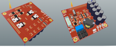
Attached a class d amplifier I'm working on, I don't have all the up front specifications, its purely a design for diy research (not commercial) its taken sometime to get the board 4 layout pcb as shown, I will be using a micro-controller and other modern techniques.
Attachments
")
What will the microcontroller do ?
I use small PIC micro's for DC protect.
Some MCU designs use a combination of "analog and supervisory", My design I will be using two smd transistors 4 passives and feed the error detected dc as a "fault" then letting the MCU do its thing, like log to flash and shutdown, other designs will try and do everything using code, my issue with this is:
1) Low level code needs to be written with careful setup of priority ISR's (probably in assembly for the best response time) it will be shared with other core timing code, and if not written correctly creates catastrophic bugs, however its possible to do everything in code, in due time this requires skills with seriously good assembly skills and understanding of the chip machine architecture in use. ARM, MIPS it doesn't matter really.
2) You need to write IIR filter routines to perform constant scanning all the time keeps the MCU busy and may block other tasks from carrying out the work. its complicated code to master first time, less time critical tasks can be programmed instead.
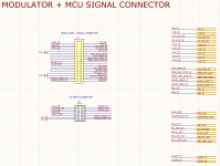
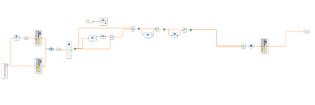
See attachment, shown are the signals Iv'e elected (more may follow) for my MCU I'm attending to read into the MCU. Not shown are the control lanes for the DSP I'm just going to use a off the shelf DSP like the ADAU 1401, I have all the DSP comms code and sigma dsp structure working, I'm struggling to find the time to put this all together. But it shall be done.
Attachments
I use a 8 pin PIC with four resistors to detect DC.
The resistors split the input voltage so that when the input voltage goes above 2v it knows there is -ve there. The other input splits the negative going voltage.
If the PIC sees either for >250mS it shuts of a relay.
The PIC also detects mains so can shut down the relay if mains goes.
This is a long way from what you are doing with your all singing, all dancing system.
You have a lot of inputs and so need a much more complex micro.
I also did another 8 pin PIC system with over current detect as well as DC detect but I used an op amp to process the over current signal.
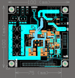
Attached: Progress for the amplifier's 4-Layer design PCB, lots of small tweaks and core routes are still outstanding. (I wanted a better pcb route strategy so I reworked 90% of original layout, I'm happy with the one I have now.
PCB Progress
- Finalization for all analog + digital signals.
- Bus-supply rails routes has been finalized.
- 70% External modulator + micro-controller pins has been.
- Completed local regulation.
For the DSP Subwoofer.
- Volume: -60dB – 0dB (1dB/step)
- Phase adjust: 0° – 180° (1degree/step)
- Parametric EQ: PEQ Frequency: 20, 22, 25, 28, 30 – 200Hz (1Hz/step)
PEQ Boost: -12.0 – 6.0dB (0.1dB/step)
PEQ Q Factor: 0.2 – 10.0 (0.1/step)
- LP/HP filter: 30Hz – 200Hz (1Hz/step) / LP Slope: 6dB, 12dB, 18dB, 24dB
- Room Gain Comp: N/A (busy with this)
DSP: Typical IIR/FIR structure, 56-Bits, Sampling rates of up to 192 kHz supported.
Subwoofer Amplifier:
- ~ 800 Watts RMS
- Auto switch off
- DC protect
- OV/UV/OT/UT/OC protection
- Analog input fully differential inputs.
Bluetooth controlled + Remote controlled. (Mobile app). (future)
Attachments
Last edited:
- Status
- This old topic is closed. If you want to reopen this topic, contact a moderator using the "Report Post" button.
- Home
- Amplifiers
- Class D
- coming soon.