I ordered one and it should arrive between 12/12 - 12/24. Could always start a thread in the Digital Line Level forum. I'll be ordering 3e's 4 channel TPA3251 amp too as its specs look better than competing Sure, etc. My only concern for the 3e DSP board is their use of the line level drivers to boost the output of the ADAU1701 DACs - at low input levels (see the DSP datasheet) the line drivers add distortion. You can see it in the line driver's (DRV632) datasheet too.
Interesting! I have ordered the 4x100w amp as well. It'll be interesting to see how it pans out.
I have both this and the Sure ADAU1701 programmer board so hopefully one of them will work with the 3e DSP boards I have for this amp:
1pcs EZ USB FX2LP CY7C68013A USB logic analyzer core board+Source Code-in Integrated Circuits from Electronic Components & Supplies on AliExpress
And yes, I thought about starting a new thread depending on how I get on, its difficult to estimate the scope of a thread when starting a project.
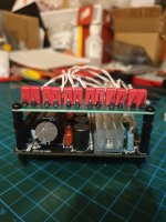
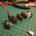
Balanced input daughter-board complete!
I ended up using Wima film caps.
I think I will design the crossovers on my MiniDSP 8x8 using the balanced outs and this amp with these inputs. I can't imagine the DSP board will alter the sound that much, the amp will be the bigger factor I imagine.
I ended up using Wima film caps.
I think I will design the crossovers on my MiniDSP 8x8 using the balanced outs and this amp with these inputs. I can't imagine the DSP board will alter the sound that much, the amp will be the bigger factor I imagine.
Attachments
Updates:
* DSP board connects using my Sure programmer, brilliant!
* I'm investigating wooden cases and have come to the conclusion some sort of shielding is in order, perhaps in the form of copper or aluminium tape. BUT, how will the bluetooth/wifi aerial of the Arylic Up2Stream Pro get coverage? Hmmmm.
Also, the only metal protruding parts will be speaker terminals and aux in. Do these need to be earthed? I read elsewhere about using a CL60 between star ground and earth but my set up will be a bit different with lots of DC-DC isolated grounds.
I am using the enclosed Mean Well LSR-350-24 PSU.
* Cooling. I'm going to need additional cooling if I am going to using a wooden case.
These look just the ticket and will be about the internal height of the case. I plan to have one at the rear of the case pulling air across the components from peg board style holes in the front half of the bottom of the case. I plan to have a second blowing air down the fins of the amplifier.
Gelid Silent 6 Case Fan 60 x 60 x 15,5 mm Hydro Dynamic Bearing 12 V 3200 rpm 24 dBA 3 Pin Molex CE RoHS: Amazon.co.uk: Computers & Accessories
These are PWM fans so I take it simply varying voltage will not vary the speed? Is there a cheap and simple way to control fans speeds that doesn't mean introducing another board?
My deadline of X-Mas isn't looking likely but my friend will be fine with that!
Last edited:
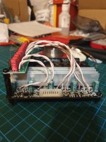
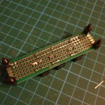
The low current power distribution board is done!
Neil, I took your advice and splashed out on some DC-DC isolators that went straight from 24v to 5v and 12v, respectively.
I ran the 24v down all + and - with bus bars (?) and jumped across to dupont headers for easy assembly/dismantling of the individual boards. The 3e DSP boards only have headers for 12v and I couldn't be bothered to desolder the USB socket to access the 5v.
Having spoken to Arylic and one of their engineers the Up2Stream Pro board only uses 300ma despite the recommended 5v/1a PSU. I tested it this evening and it works fine with a 2w/400ma supply and wifi coverage didn't seem to be effected!
I was feeling miserable when I got in from work today but making this little board put me in a good mood again!
Attachments
* I'm investigating wooden cases and have come to the conclusion some sort of shielding is in order, perhaps in the form of copper or aluminium tape. BUT, how will the bluetooth/wifi aerial of the Arylic Up2Stream Pro get coverage? Hmmmm.
The wood case will attenuate the WiFi/Bluetooth signal somewhat, depending on how much wood there is and the moisture content. That module is just 2.4G, which is about the same frequency as used by a microwave oven. As you know, water absorbs those frequencies and gets hot in a microwave oven, so any moisture in the wood will attenuate the signal. And, obviously, any copper or aluminum foil will reflect the radio signal, effectively blocking it.
I always throw away those stick-on antennas and buy a U.FL to SMA cable so that I can use a standard WiFi antenna on the outside of the chassis. The range improves dramatically and it looks nicer. But make sure you get the right sex/polarity to match the antenna. It's best to buy the antenna and cable as a kit so you know they will match.
Cheers Neil, good shout.
I have had these in my drawer at work and forgot about them, will they be appropriate for bluetooth as well? They are standard wifi aerials from the back of defunct machines.
I'll pair them with these:
20cm IPEX To SMA (Male) 1.13 Cable Antenna Pigtail Cable Coaxial | eBay
Attachments
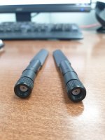
Those aerials should work well. The mating cable looks right.
I've had some issues ordering by description (RP-SMA vs SMA, vs female/male housing, vs female/male pins), but as long as the picture is accurate you should be OK.
Once you have the SMA connector available on the chassis, you can use a larger antenna or an antenna with an external mount if you need more gain. That's sometimes important with these WiFi modules to minimize interference and prevent dropouts.
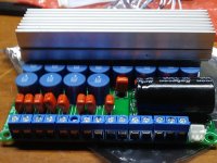
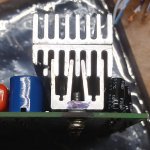
To improve the heat dissipation on my board I purchased 3 heatsinks for $1.13 from Ebay (LINK). They’re the same length as the original heatsink and have adhesive backing on their flat side. I removed the original heatsink, turned one of the new heatsinks upside down and used a vise to force them together. Then I mounted a second heatsink right side up using the two adhesive covered backs (see first picture). The only complication was the outer fin of the upside down heatsink hit the tops of the blue inductors so I used a hacksaw to shorten that fin before mounting the final heatsink.
In my haste I forgot to wipe the heatsink fins with thermal paste before using the vise to force them together. The board still runs significantly cooler than just the original heatsink so I’m satisfied how it turned out.
In my haste I forgot to wipe the heatsink fins with thermal paste before using the vise to force them together. The board still runs significantly cooler than just the original heatsink so I’m satisfied how it turned out.
Attachments
Thanks for all the suggestions and info. I had a break from this project but I'm back on it.
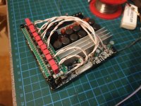
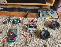
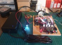
The system works as designed, which is nice! Wifi source, DSP and amp all working from the same PSU with balanced connections. I might try the I2S connection next. But it hasn't made it any further than the image below - I need to get on the woodworking stage as spring approaches!
The system works as designed, which is nice! Wifi source, DSP and amp all working from the same PSU with balanced connections. I might try the I2S connection next. But it hasn't made it any further than the image below - I need to get on the woodworking stage as spring approaches!
Attachments
Hi all!
I'm starting to get a bit worried about having the power supply in a DIY box so I have been looking at self contained units so 24v is the only power source in the box.
These are fairly cheap:
https://uk.farnell.com/mean-well/el...41996954789|&CMP=KNC-GUK-GEN-SHOPPING-2943984
http://www.farnell.com/datasheets/2...MI3eT6_Jvv5wIVU4fVCh2ttQfOEAQYASABEgJU4PD_BwE
I don't understand what the dimming feature of the unit would have in terms of ramifications for use with this amplifier. Is it a bad idea?
Sticking with a well known company is preferable as I am making this for a friend - I would be quite happy to use an AliExpress special in my own home.
Any thoughts would be appreciated.
G.
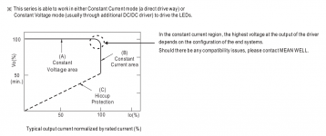
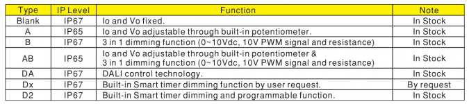
As it says the LED dimming is PWM, on off 1KHz-3KHz, likely to be a mosfet switch. I would assume that the units not specified with that option will not have the component(s) in place.
I would raise one concern over the fact that the basic supply and presumably others in the range incorporates some form of load line shaping that might not play nicely with a dynamic load such as an amplifier.
Then again... current limiting is current limiting. You will have to suck it and see.
...
I would raise one concern over the fact that the basic supply and presumably others in the range incorporates some form of load line shaping that might not play nicely with a dynamic load such as an amplifier.
Then again... current limiting is current limiting. You will have to suck it and see.
...
Attachments
As it says the LED dimming is PWM, on off 1KHz-3KHz, likely to be a mosfet switch. I would assume that the units not specified with that option will not have the component(s) in place.
I would raise one concern over the fact that the basic supply and presumably others in the range incorporates some form of load line shaping that might not play nicely with a dynamic load such as an amplifier.
Then again... current limiting is current limiting. You will have to suck it and see.
...
Thanks for the input, man! Although I couldn't have put it so specifically as you they were my concerns, also. Though, isn't a switched supply PWM anyway? Maybe I've revealed my lack of knowledge there!
I wondered if the current control was set to max it would disengage the function.
They are £30 in the UK, delivered vs £65 for the fixed voltage version, not sure if it is worth the risk, the budget for this project is maxed out as it is and I don't want to waste my friends money
")
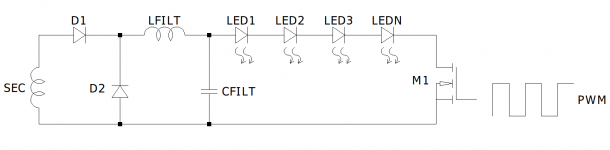
Yes it is a switch mode power supply and will use PWM to produce the regulated power for the LEDs. The PWM section mentioned in the data sheet is an additional function provided to dim the LED string. It seems you are suggesting that the supply with the PWM function is cheaper than one without it, TYPE BLANK Vo and Io fixed with no PWM function.
Anyway it should be possible to set the PWM to 100% in effect turning the output on all of the time and Vo/Io to maximum. It is also highly likely that my interpretation of the operation is completely wrong.
...
Anyway it should be possible to set the PWM to 100% in effect turning the output on all of the time and Vo/Io to maximum. It is also highly likely that my interpretation of the operation is completely wrong.
...
Attachments
I like the Meanwell UHP series because they are very compact and easy to heatsink to the chassis baseplate. That power supply might give you some more options if you still want it inside the chassis. I used it for this amp.

Thanks for the input guys.
Perhaps I should explain my rationale for wanting an external PSU and some proposed changes to the original plan....
- Move from a 6 channel system to a 4 channel system. 1 chip (2x50w) for the satellites and the two bridged chips (2x100w) for the two subs. This way I can make the simplest passive XO for the satellites with minimal parts count and correct the response with DSP, globally on the stereo pair. I searched for hybrid passive/active crossovers on here today and found close to zero examples.
(This is also dependant on final measurements taken from the satellites once the UK weather lets me finish them)
- Use an external PSU such as Security Check for two reasons: SAFETY - a wooden box and mains power gives me the willies. Also I don't like the idea of exposed mains terminals and line level cables in the same enclosure. Having the safety of a manufacturers power adapter makes me feel better.
SPACE - the original design was getting way beyond what I proposed to my friend and I want to make it ergonomic to her surroundings.
- Employing a hybrid passive/active XO has two benefits. I can use one less XO board and it also requires a less powerful PSU. I have the LSR-250-24 (350w obvs) already but the GST220A24 (220w) should suffice with one chip down. If I understand Class D correctly I should remove the conductors from the unused chip.
Sorry if that's a bit wordy but it's good for me to get my thoughts down after a lot of thinking!
3E DSP Board I2S Output
Graham –
Here’s how to hook up the DAC to the 3e Audio DSP, step-by-step.:
First you need to configure the 1701 so the multipurpose GPIO pins are outputting I2S data. The 1701 supports up to 4 L-R pairs (8 individual channels) of I2S data in addition to the four DACs. The pins we’re interested in configuring are:
MP6 = Sdata_out0; MP7 = Sdata_out1; MP8 = Sdata_out2; MP9 = Sdata_out3
MP10 = In_LRCLK_Out; MP11 = In_BCLK_Out
We only need one of the data pairs so let’s pick MP6 as our data source. Go to the “Hardware Configuration” tab in SigmaStudio, select the “ADAU1701” block so it’s outlined in green, right click and select register window. Look for the “GPIO” section. Click on the MP6 drop down check mark and select “Output Sdata_out0”. In the same way select “In Lrclk_out” for MP10 and “In Bclk_out” for MP11. Some or all of these might already be set up. Then look for the “Serial Output 1” section and select the “Master Mode” option. All the other default I2S settings worked for this DAC.
Note for those using the 3e Audio SigmaStudio source code:
You’ll notice that MP6 and MP7 are configured as “Input GPIO Debounce”, MP8 is configured as “Aux_ADC_3” (the treble pot) and MP9 is configured as “Aux_ADC_2” (the volume pot). So all four Sdata_out GPIO pins seem to be in use. The MP6 and MP7 pins may be used by the “Auto Source Selection” and “Auto Mute” blocks. It’s hard to tell since the source code for those blocks aren’t supplied. I sent an e-mail to 3e Audio about the subject today.
Next we need to add to the digital outputs to the SigmaStudio schematic. Go to that tab and drag the “output” control (found in the “IO” section) onto the schematic. From the control’s drop down list choose “DIG0. Repeat and select “DIG1”. These are the SDATA_0 Left and Right channels respectively. After that you connect those outputs just like a DAC output.
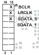
For the hardware connections: My previous post (#16) shows where to get the DAC 5 VDC. I attached a diagram showing where the other connections (BCLK, LRCLK and Data) are found on the DSP’s J5 connector. You can also get the ground from any of the even numbered J5 pins. I used pin-to-pin jumpers in my initial test.
You should be ready to go! Just remember the DAC’s max output is 2 Vrms which is less than the DSP DAC outputs.
Attachments
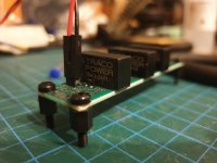
Small steps but it's getting there!
Instead of enlarging the heat sink (mainly due to me not thinking ahead and mounting the balanced inputs above the current sink) I am going to go for a constant slow draw of air across the board. The air will be pulled from the front end of the enclosure through the opposite parallel panel that the boards are mounted on. This will pull it down and across the DC isolators that get warm and then down the fins of the amp. Hopefully this will be enough.
I am using a Gelid Silent 5 50cm fan which, I would like to say (outside of an Amazon review - it would grate on me that I assisted Bezos any futher) that it is NOT silent. I may down the speed to quieten it once enclosed.
Attachments
- Home
- Amplifiers
- Class D
- 6 Channel TPA3116 + DSP