It looks like there are two versions of this board--one with two bulk capacitors and 3 screws holding the heatsink, and a newer version, with just one bulk capacitor and 5 screws in the heatsink.
I've taken the heatsink off of the "original" version with 3 screws. There is thermal paste on each chip that makes it stick to the heatsink, but it's pretty easy to break that bond by twisting the heatsink a bit. It's gooey stuff--the same as what is used on many CPU's, but it doesn't harden.
If they used thermal epoxy on the new ones, you might need heat or a solvent to break down the epoxy. The thermal epoxy that I've seen is the same type as the 5-min epoxy, which softens around 180C. Heating to that temperature would probably damage the board. However, isopropyl alcohol or ethanol would probably attack the epoxy without doing any board damage. There are some other candidate solvents listed here.
But cripes, with 5 screws, why would they also use epoxy? I'm guessing you should be able to remove the heatsink with moderate force, directed in a way that wouldn't put too much stress on individual solder joints.
Last edited:
OK, mine arrived today, also. I ordered from a place that showed the picture of the old version, but I got the new version with 5 screws in the heatsink.
And yep, the heatsink is glued onto the chips with thermal epoxy. That's the bad news. The good news is that thermal epoxy isn't very strong. It's hard, but somewhat rubbery due to the embedded thermal paste. I crammed a screwdriver between the inductors and the heatsinks and also pried between the heatsink and the circuit board. It didn't take that much effort to pop off the heatsink. I'm not going to guarantee that you won't screw up the board, but for me it wasn't a big deal.
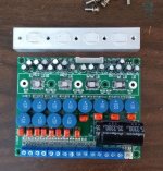
I didn't have our good camera charged and ready--this is just a budget cell phone pic. If you want a higher rez image, it will take a couple of hours...
And yep, the heatsink is glued onto the chips with thermal epoxy. That's the bad news. The good news is that thermal epoxy isn't very strong. It's hard, but somewhat rubbery due to the embedded thermal paste. I crammed a screwdriver between the inductors and the heatsinks and also pried between the heatsink and the circuit board. It didn't take that much effort to pop off the heatsink. I'm not going to guarantee that you won't screw up the board, but for me it wasn't a big deal.
I didn't have our good camera charged and ready--this is just a budget cell phone pic. If you want a higher rez image, it will take a couple of hours...
Attachments
Thanks all! I left it on the radiator for 15 mins and took your scary advice Neil ")
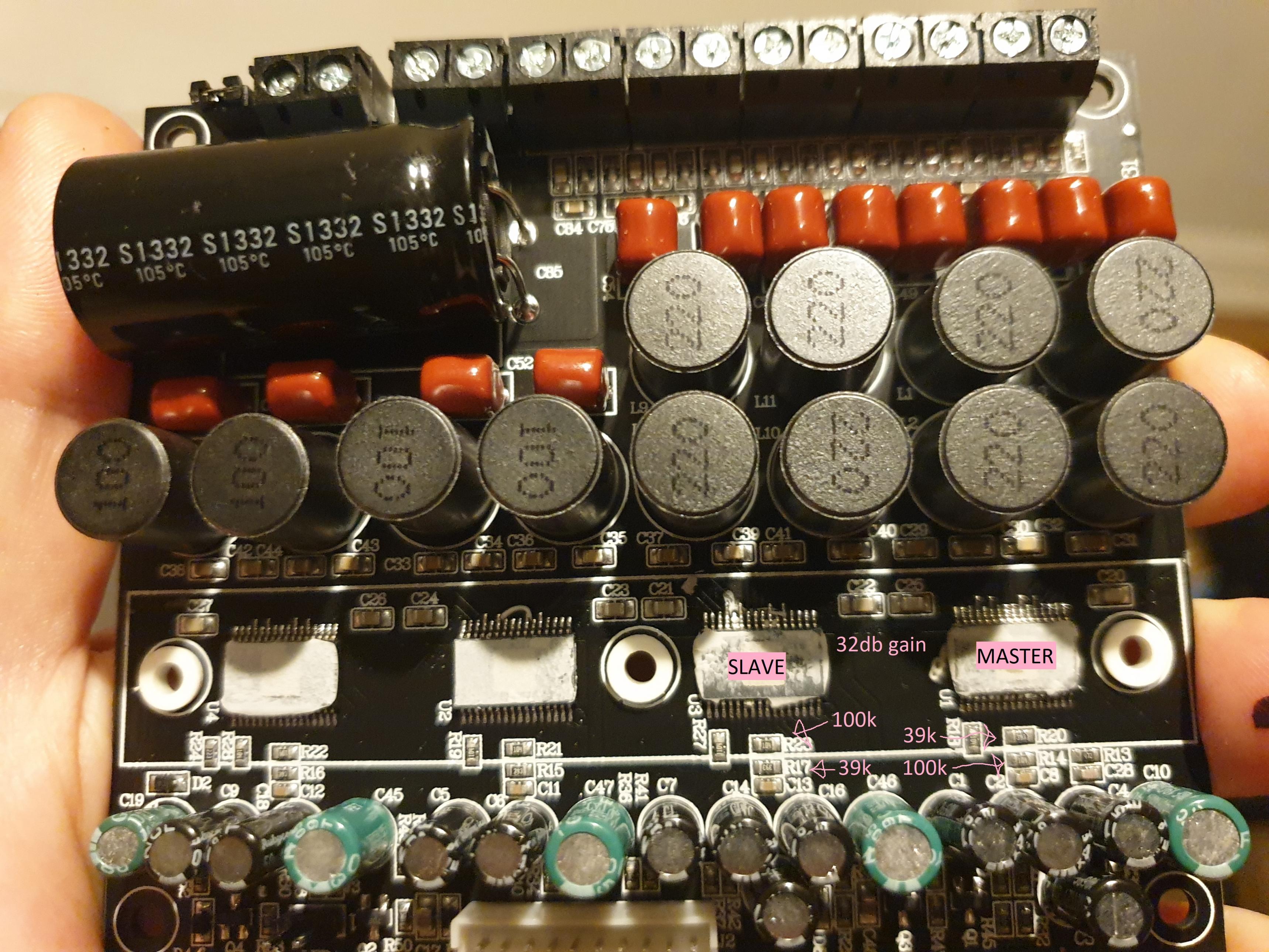
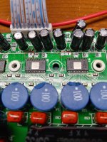
Looks like it is set to 32db gain which is too high, obvs.
I only have 0805 resistors and these look smaller. Maybe 0603? Will I be able to get 0805 mounted? I'll need a finer tip for my iron.
How shall I remove the thermal gunk on there? Or should I just leave it on? I have thermal plaster and paste for the final mounting.
Attachments
The thermal epoxy scrapes off fairly easily with a razor blade, and then follow up with denatured alcohol (ethanol) or full-strength rubbing alcohol (isopropyl alcohol).
You can make your own thermal epoxy by mixing 5-minute epoxy with any good thermal paste. I use equal parts of epoxy and thermal paste. But you could also just use straight thermal paste, since those 5 screws should hold everything in place just fine.
Yep, 32dB gain is a bit high. That results in a voltage gain of about 40. If you are using a DSP like the ADAU1701 with a voltage output of .9v, 32db is OK for a lot of applications. However, I'm using the amp for near-field listening, and the bass channels are providing 2V output from the DAC attached to the DSP, so I want to back off the gain by at least 6dB. Just way too much hiss when I'm listening from 3 feet away...
I'll document the changes to this board when I get around to writing up the monitor stand project at Audiodevelopers.com. It might be a while before I finish that write-up, since much of the project centers around some new software that I am still working on.
Cheers Neil, I look forward to reading about your progress. I'll have a good read of your site today as well.
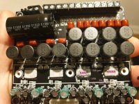
I cleaned it all off with IPA, I just used thermal grease for the time being whilst there is the possibility the sink needs to come off and on.
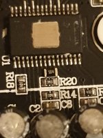
Looks like 0805 will just fit on the pads. (resistor shown above R20 is not correct value just first I could find. It'll take some ninja skills!
Turbowatch2 - you'll be glad to know I ordered these to test the amp without having any channels left without load :
from PS0.35/each 0.1ohm-100Kohm 5W Resistor High Power Ceramic | eBay - 8ohm
I cleaned it all off with IPA, I just used thermal grease for the time being whilst there is the possibility the sink needs to come off and on.
Looks like 0805 will just fit on the pads. (resistor shown above R20 is not correct value just first I could find. It'll take some ninja skills!
Turbowatch2 - you'll be glad to know I ordered these to test the amp without having any channels left without load
:from PS0.35/each 0.1ohm-100Kohm 5W Resistor High Power Ceramic | eBay - 8ohm
Attachments
hi graham
that is what i use :it comes from car audio testing something- cheap and 50W resistors 4x.
https://www.amazon.de/AMAZENAR-Last...kfz+8ohm+50W+widerstand&qid=1573199467&sr=8-1
chris
that is what i use :it comes from car audio testing something- cheap and 50W resistors 4x.
https://www.amazon.de/AMAZENAR-Last...kfz+8ohm+50W+widerstand&qid=1573199467&sr=8-1
chris
Cheers Chris!
I had already ordered the above. Do I need the higher rated ones even if I am letting the channels with them connected to sit idle? I need to be able to access the four "50w" channels to begin with to design my mid/tweeter crossover in SigmaStudio and won't have subs connected so if no signal is going to them I can just have the loads connected so the amp doesn't go t*ts up?
I had already ordered the above. Do I need the higher rated ones even if I am letting the channels with them connected to sit idle? I need to be able to access the four "50w" channels to begin with to design my mid/tweeter crossover in SigmaStudio and won't have subs connected so if no signal is going to them I can just have the loads connected so the amp doesn't go t*ts up?
Why would you think the amp would fail without a load? I saw one thread where the output capacitors failed without a load, but the op was using capacitors that didn't have adequate voltage rating and there was no damping in the filter. These amps use 63V capacitors in the output filter, along with an extra pole with a 3.3 ohm damping resistor. That combination should allow safe, reliable operation with no load.
I can check the output with a scope later on to see if there is excessive voltage spikes with no load, but right now I don't see any reason to be concerned. I've run it with no load, so I know that it can be done without failure. According to the block diagram in the datasheet (section 7.1), this amp includes diodes on the output transistors to snub oscillations that go above PVDD or below GND, so the chip itself should be protected. As long as the output filter components are properly selected--and they appear to be for this amp--there should be no issues without a load.
I can check the output with a scope later on to see if there is excessive voltage spikes with no load, but right now I don't see any reason to be concerned. I've run it with no load, so I know that it can be done without failure. According to the block diagram in the datasheet (section 7.1), this amp includes diodes on the output transistors to snub oscillations that go above PVDD or below GND, so the chip itself should be protected. As long as the output filter components are properly selected--and they appear to be for this amp--there should be no issues without a load.
Last edited:
Hi Neil,
you are 100% right. "Should" be no problem with any modern amp.
Some amps here, where we talk about cheap, have failed and burned a chip, driven without a load.
So, better be save, use the amp as intended, with a load, than trust the unknown constructor and be sorry.
you are 100% right. "Should" be no problem with any modern amp.
Some amps here, where we talk about cheap, have failed and burned a chip, driven without a load.
So, better be save, use the amp as intended, with a load, than trust the unknown constructor and be sorry.
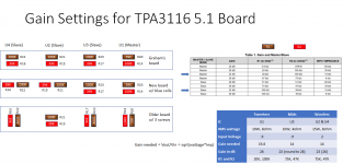
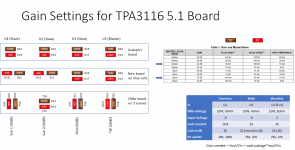
I started making the changes to reduce the gain on this board, and realized that there are at least 3 different versions of the board. They all appear to use the same schematic, but the resistors that set the gain are in different places on all 3 boards. I used the picture that Graham posted for his board, and found that two of the three boards that I own are different. The gain resistors are either parallel to the chips or perpendicular--depends on the PCB. See the attached drawing that shows the 3 different layouts.
In order to determine the necessary gain for my project, I calculated the output required to reach the maximum rated wattage of the driver, and divided that by the input voltage. I used 1/2 the maximum input voltage to give me extra headroom. It turns out that the best gain for my application would be between 20dB and 26dB, so I went with the higher figure. The factory setting of the board is 32dB, which might be OK for really inefficient speakers, but there is too much "hiss" for nearfield listening with efficient drivers. I'll finish the mods tomorrow--I wanted to document the boards first before I started removing the parts.
I screwed up the first round of changes by assuming that I could just change the 39K resistor for all the amps. However, that is only true for the "Master" chip. For the other chips, you need to change two resistors, which makes the job more challenging. I used a 0805 because that was all I had for the master channel, and it wasn't too hard to cram onto the 0603 pads. But it will probably be easier to use 0603's. Given the way my board is laid out, it is too hard to fit a hot air nozzle between the other parts, so I'm using a fine conical tip.
BTW, the most recent board I got uses a Rubycon YXF bulk capacitor. Assuming it isn't a fake, that is an excellent part: 10,000 hrs. lifetime at 105C. No sane reason at all to consider changing it. The board has low ESR ceramic caps on either corner of the TPA3116, so the lifetime/thermal rating of the bulk cap is much more important than ESR.
Attachments
Nice work Neil!, keep us updated. It would be great to see your soldering world. I will be using the standard chisel tip on my Antex X25.
In regards to the bulk cap I would still like to change mine. I have a 10,000uf nichicon low esr, would that be appropriate?
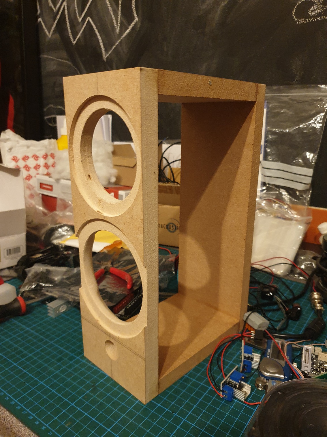
I am no further in the electronics side of this project as I am working on the satellites and subwoofer atm. These two baffles took ages and ended up with a 1mm clearance for the tweeter recess. It took me 5 attempts to make 2 baffles. 107mm wide:
Anyway, I am thinking of abandoning the random bluetooth board and trying an arylic up2stream. Has anyone got any experiences with them? They aren't cheap by comparison.
Up2stream Pro WiFi&Bluetooth HiFi Audio Receiver Board
– arylic
I2S or analogue - Wifi - bluetooth - music app support - airplay - dlna.
In regards to the bulk cap I would still like to change mine. I have a 10,000uf nichicon low esr, would that be appropriate?
I am no further in the electronics side of this project as I am working on the satellites and subwoofer atm. These two baffles took ages and ended up with a 1mm clearance for the tweeter recess. It took me 5 attempts to make 2 baffles. 107mm wide:
Anyway, I am thinking of abandoning the random bluetooth board and trying an arylic up2stream. Has anyone got any experiences with them? They aren't cheap by comparison.
Up2stream Pro WiFi&Bluetooth HiFi Audio Receiver Board
– arylic
I2S or analogue - Wifi - bluetooth - music app support - airplay - dlna.
Attachments

Nice work Neil!, keep us updated. It would be great to see your soldering world. I will be using the standard chisel tip on my Antex X25.
I used to use a 40-year-old Weller TCP iron but it crapped out last month and I got a WE1010NA. I have no problems with 0603 resistors--I changed all of the ones on my board in about 20 minutes. You need good tweezers and a head loupe with at least 2X magnification.
In regards to the bulk cap I would still like to change mine. I have a 10,000uf nichicon low esr, would that be appropriate?
As I said in a previous post, this is not a good idea. The large bulk capacitor with low ESR can degrade the transient performance of the feedback loop in a switching supply and it can result in the power supply going into current limiting mode in some cases. Read section 2.3 and 2.5 of this tech note. Don't worry about the bulk capacitor--the high frequency decoupling is far more important in a class D amp. The bulk capacitor is not important if you are using a switching power supply--in fact, TI only recommends using a 100uF bulk capacitor for each TPA3116.
Anyway, I am thinking of abandoning the random bluetooth board and trying an arylic up2stream. Has anyone got any experiences with them? They aren't cheap by comparison.
Up2stream Pro WiFi&Bluetooth HiFi Audio Receiver Board
– arylic
These boards use the same Linkplay modules that are in the Dayton WBA31, the Muzo Cobblestone, and a lot of other brands--see the Linkplay site for all of their partnerships. They are excellent--mature products that are fun to use and they provide excellent audio quality. The only drawback is that they need to buffer the WiFi audio, resulting in a 1 to 2 second delay. But the Up2stream version has low-latency Bluetooth, so you can also use the module to play back real-time audio such as TV's. I've got a number of projects using the Dayton modules at Audiodevelopers.
Last edited:
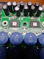
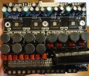
I have the same 6 channel board as Neil, except mine has 22 uH output filter inductors on the 4 stereo outputs instead of Neil's 10 uH output filter inductors. I would be willing to bet all the other circuitry is identical. The board, as delivered, is set for 32 dB gain. I verified the 4 TPA3116 chips are wired as master/slaves as I hoped so all 4 chips are synch'd together. The master chip is the leftmost chip when the amplifier is positioned with the output inductors closest to you.
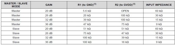
I wanted 20 dB gain so I made the modifications below. Do note that resistor values for TPA3116 gain settings differ between master and slave mode chips (see the first attachment from the TPA3116 datasheet). Here are the original resistor values on the board using the datasheet R2 and R1 designators. The designators in parenthesis are the board identifiers. The slave chips are numbered left to right with slave1 next to the master chip. The photos show the resistor locations on the board.
...........R1..........R2
Master 39K (R20) 100K (R14)
Slave1 100K (R23) 39K (R17)
Slave2 100K (R21) 39K (R15)
Slave3 100K (R22) 39K (R16)
To set the master chip to 20 dB gain I just removed R2 (100K, R14). The table lists that R1 (i.e. R20) should also be changed to 5.6K, but R1 and R2 just create a voltage divider network and without R2 the value of R1 is really unimportant. So I left it unchanged.
To set the 3 slave chips to 20 dB I removed the 3 100K resistors (R23, R21 and R22) and replaced them with 39K resistors. The table lists that both R1 and R2 should be 51K, but the important point is that they are the same values so they divide the voltage (GVdd) to one-half its value. So my slave chips have both R1 and R2 set to 39K.
I didn't have any problem removing the heat sink after I removed the mounting screws as only thermal paste held the heatsink to the TPA3116 chips. Do note that some of the screw holes are isolated with grommets and others are meant to be grounded. Don't move or lose the grommets! I cleaned the heatsink and chip tops and used fresh thermal paste when I remounted the heatsink.
Hope this helps! I'm not a big SMD fan when it comes to soldering so that's why I took the approach of minimizing the number of resistor changes. I do have pre and post power/distortion measurements and the board works great at 20 dB gain. It still runs hot as Neil has discovered. I'd like to find a more substantial heatsink, but's that another adventure.
Attachments
Last edited:
It looks like there are a number of variations of this board. But fortunately, they all use film caps in the output filter, reasonably sized shielded inductors and properly placed decoupling capacitors for the TPA3116. Those are the key ways that a manufacturer could screw up a TPA3116 design, and so far this board looks like a real winner, in spite of the variations.
I changed the gain on 3 of the chips to 26dB and set the tweeter channel to 20dB gain. That got rid of most of the background hiss, although I could have gone with 20dB for all channels. That's using my stereo 3-way ADAU1701 board, which uses the ADAU1701 DAC's (.9V output) for the mid and tweeter channels and a separate PCM5102 DAC (2V output) for the left and right "sub" channels. The final resistor values are shown in the updated chart.
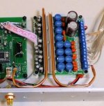
The heat can be removed using heat pipes. The 4mm flat heat pipes from Digikey fit into the heatsink fins rather well. They are fairly easy to bend. I bought a small tubing bender at Home Depot a while back that works great on the round pipes, but you can also use it on the flat pipes if you make some shims from wood blocks. I clamped the heat pipe to the front panel of my chassis, and I used a 50-50 mix of 5-minute epoxy and silicon grease to fill the gaps. The heat pipes are very effective at getting rid of the heat.
Also, I had a ground loop that caused a lot of buzzing when I connected the amp to a PC. But that was because the heat pipes were grounded and the screws holding the heatsink to the board had shorted to the ground plane on the back of the board. I used fiber insulators on those mounting screws to eliminate the ground loop.
The heat pipes in the picture are about 2" too long, but you can buy shorter ones. This is the Digikey link: ATS-HP-F6L200S23W-310 Advanced Thermal Solutions Inc. | Fans, Thermal Management | DigiKey . I modified these to make the clamp for the heat pipes: MAX08NG Aavid, Thermal Division of Boyd Corporation | Fans, Thermal Management | DigiKey
I changed the gain on 3 of the chips to 26dB and set the tweeter channel to 20dB gain. That got rid of most of the background hiss, although I could have gone with 20dB for all channels. That's using my stereo 3-way ADAU1701 board, which uses the ADAU1701 DAC's (.9V output) for the mid and tweeter channels and a separate PCM5102 DAC (2V output) for the left and right "sub" channels. The final resistor values are shown in the updated chart.
The heat can be removed using heat pipes. The 4mm flat heat pipes from Digikey fit into the heatsink fins rather well. They are fairly easy to bend. I bought a small tubing bender at Home Depot a while back that works great on the round pipes, but you can also use it on the flat pipes if you make some shims from wood blocks. I clamped the heat pipe to the front panel of my chassis, and I used a 50-50 mix of 5-minute epoxy and silicon grease to fill the gaps. The heat pipes are very effective at getting rid of the heat.
Also, I had a ground loop that caused a lot of buzzing when I connected the amp to a PC. But that was because the heat pipes were grounded and the screws holding the heatsink to the board had shorted to the ground plane on the back of the board. I used fiber insulators on those mounting screws to eliminate the ground loop.
The heat pipes in the picture are about 2" too long, but you can buy shorter ones. This is the Digikey link: ATS-HP-F6L200S23W-310 Advanced Thermal Solutions Inc. | Fans, Thermal Management | DigiKey . I modified these to make the clamp for the heat pipes: MAX08NG Aavid, Thermal Division of Boyd Corporation | Fans, Thermal Management | DigiKey
Attachments
Last edited:
Looks plenty good. Congrats.
I like the layout of the gain resistors your board, because there is enough room to aim a hot air nozzle on the resistors without causing other problems. With the hot air, those tiny resistors magically align themselves with the pads and make perfect looking joints. On my two boards, the resistors are too close to the capacitors to use a hot air rework station.
I can't tell what brand of bulk capacitor is used on your board, but I can see that is rated at 105C. That's a good sign--the long lifetime caps are usually rated at 105C vs 85C. One of my boards used a single Rubycon long life bulk capacitor and the other board was the older configuration that used 2 Samwha caps. Samwha Capacitor Group was a joint venture with Nichicon--they are reputable and are used in a lot of consumer electronics.
Cheers Neil. It took a couple of attempts.
The bulk cap is the same as your Rubycon. I have done some shopping about but I can't find a 35v 3300uf YXF for sale anywhere. Am I missing something? If it was real it would be about £6 which would account for a large amount of the BOM.
The bulk cap is the same as your Rubycon. I have done some shopping about but I can't find a 35v 3300uf YXF for sale anywhere. Am I missing something? If it was real it would be about £6 which would account for a large amount of the BOM.
35YXF3300MEFC18X35.5 Rubycon | Capacitors | DigiKey
It's not a stocked item at Digikey, but it can be ordered. $1.45 in quantities of 200. Same story at Mouser: non-stocked and $2.73 in single quantity.
Sure, there's always the possibility of fakes, and it might be fun to open one of these up to make sure it is legit. But really, from an engineering perspective, the bulk capacitor doesn't do a whole lot if you are using a switching power supply, so I don't have much motivation to investigate any further.
- Home
- Amplifiers
- Class D
- 6 Channel TPA3116 + DSP