Hi there,
I think people who works in 'Analog or Power electronics" understand this issue.
I am having a project on, "3 phase power Calibrator"
Like my previous post I was trying to go with a ClassAB for current and voltage amplifier.Lets take a look on a linear amplifier
Comparable study shows, ClassAB is less suitable than ClassD.
ClassD is a voltage source device, so current transformer may not be use, Lets take a look on a linear amplifier
I think potential transformer can be use with ClassD, https://www.element14.com/community/thread/73845/l/classd-amplifier-for-transformer
Since my project need to get Current transformer output, kindly suggest me what should I do.
I'am not sure with this solution, ,https://e2e.ti.com/support/motor-drivers/f/38/t/848028
Hi,
I hope to understand your question correct.
The class D amplifiers we normally consider do not have post filter information and they are of the voltage output (voltage control) type of amplifiers.
Some very advanced members have designed current output (current control) amplifiers based on class AB designs. They use detection of the output current in order to control the current.
As I see it, you will need similar output current detection with a class D amplifier. How difficult it will be to have a decent current regulation with the output filter, I dare not say.
Last edited:
Hi,
I hope to understand your question correct.
The class D amplifiers we normally consider do not have post filter information and they are of the voltage output (voltage control) type of amplifiers.
Some very advanced members have designed current output (current control) amplifiers based on class AB designs. They use detection of the output current in order to control the current.
As I see it, you will need similar output current detection with a class D amplifier. How difficult it will be to have a decent current regulation with the output filter, I dare not say.
Well said Sir.
Looks like without ClassAB, there would be no solution for CT.
Now lets come to the point
1. My voltage and current amp circuit is slightly different.
2. In current amp, at OPA551, input signal is feed with reference to " ground". A series RC element 13k, 1uF after that a 1k ( one end grounded) are connected to " non inverting" input. Also a 1k one ended gound is also conneted to "inverting" input. A parallel RC element (4.7k and 47uF) is connected to feedback path. 10 ohm, 0.1 uF RC element in series are also appears between the output of the amp! In this case 2 shunt element 5W 0.5 ohm are connected and grounded in output side. No reference ground output here! (See the first link)
Darlington current booster is present!
I am using TIP147, TIP142, C1815, A1015. They are properly biasd like cascaed 3 stage, may be AB class network. More symmetric way, like one pairs AB class output is connected to others pair. Last pairs base is connected to first pairs base! At last a voltage divider of 5 ohm has been made between 2nd and 3rd outputs!
Biasing voltage of this amplifier is plus, minus 24 volt.
The problem I am facing is heating !
It is very common in robotics to use current controlled motors to apply torque by class D . I used in early 80's for a prototype door controller of a tramway .Try eeweb.com
How about this 2 ,
https://www.ti.com/product/DRV8432
and irs2092 ?
It seems I did misunderstand your aim. This is an audio forum but you are aiming at designing a commercial power calibrator. As I understand, a controlled power source for test of equipment.
I assumed operation in the full audio range but the frequency range you envisage is around the net frequencies. I believe the hint of Mr. Kokoriantz, a motor drive circuit, to be very valid. Myself, I know very little about motor drive circuits so I will leave you to other members with motor drive experience.
I assumed operation in the full audio range but the frequency range you envisage is around the net frequencies. I believe the hint of Mr. Kokoriantz, a motor drive circuit, to be very valid. Myself, I know very little about motor drive circuits so I will leave you to other members with motor drive experience.
It seems I did misunderstand your aim. This is an audio forum but you are aiming at designing a commercial power calibrator. As I understand, a controlled power source for test of equipment.
I assumed operation in the full audio range but the frequency range you envisage is around the net frequencies. I believe the hint of Mr. Kokoriantz, a motor drive circuit, to be very valid. Myself, I know very little about motor drive circuits so I will leave you to other members with motor drive experience.
My best respect goes to you.
Thank you very much.
I think maintaining a Audio speaker is different than a PT or CT.
1. Low frequency and high frequency phase shifts caused by a transformer will occur if the transformer is inside the negative feedback loop (when the output of the transformer provides the negative feedback). Then the amplifier must be compensated for these phase shifts.
2. A product with a Class-D audio power amplifier (APA) driving an output transformer with inadequate low-frequency performance may shut down when its output is stepped from zero to maximum at the start of a sine cycle. Shutdown is triggered by short circuit protection (SCP), after the first half cycle of the sine output. The root cause is saturation of the transformer core.
Any amplifier, class D, A, AB, H, G, can be made to control current. It's just a matter of arranging the feedback.
Jan
Let me post a similar application schemetic where user wanted to do some thing !
This application is for 400W, user said " I have connected additional parallel resistors to R117A, R118A, R17A, because amp was clipping, when power supply was circa 2x35V, is possible that leads of that resistors was to long?"

Now lets see other ( attached 2)
The main part of this protection circuit is a transistor FET which is connected in the power supply branch amplifier integrated circuit IRS2092. When applying a positive voltage to the control electrode of the transistor, the ground power supply voltage and the comparator halts the modulation process. The transistor FET is switched on the circuit that brings together a number of protections. One of them is check the power supply, which detects whether the supply voltage is in the range of 68 to 100 volts. If this the condition is not met, the class d protection will react. Additional protection is temperature. Circuit controls the voltage on the thermistor, which is located on the heatsink of the power switching Mosfet. Last class d amplifier protection detects the amplified audio signal at the output of the amplifier and responds when congestion or limitation.
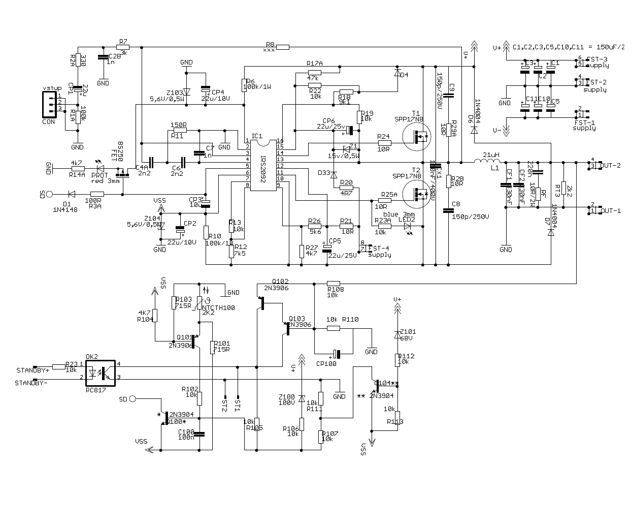
Lets disscuss how we can adapt my requirement !
- Status
- This old topic is closed. If you want to reopen this topic, contact a moderator using the "Report Post" button.
- Home
- Amplifiers
- Class D
- "Current" control is a big issue using ClassD ?