Icepower 125asx2 module hookup
Hi, I have 7 of these modules,and want to use them in bridged balanced mode with my Yamaha cxa5100 preamp, and xilica balanced crossover. I have all the amp modules at a friend's house where he will be wiring them up. I have read that there is a jumper, but I do not see a jumper on the amp boards. Can anyone post a pic of where the jumper is please?
I am hoping we can get this wired properly without me having to lug my preamp over to his house to check out all the wiring. I purchased the wiring for the BTL setup already.
Thank you
Last edited:
This build has some helpful images. I just finished up a dual mono 125ASX2 build. The mounting hole near the +/- 24 volt supply is grounded and shows continuity to the center ground pin in the +/- 24v supply and the input grounds. I jumpered the BTL sync (pin 1 in header P102) to an unused input ground (pins 6 and 7 in header P102).
As @silverD says. Also a mounting hole in the corner near to the P101 is a chassis ground, but it is in a datasheet. It should be connected to the power outlet (if you chose for a grounded 3-pin power). These two ground points are joint together when the module is mounted on the common metal base. I was caught by this secret first time.
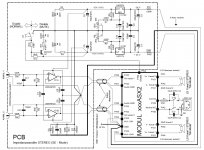
In the situation of having more than one amp module, it might be better to isolate input grounds on the modules from the chassis and deploy a circuit as shown on the picture which consist of a small resistor (R13) and a film capacitor (C6) and diodes D1, D2. What do you think about?
In the situation of having more than one amp module, it might be better to isolate input grounds on the modules from the chassis and deploy a circuit as shown on the picture which consist of a small resistor (R13) and a film capacitor (C6) and diodes D1, D2. What do you think about?
Attachments
I jumpered the BTL sync (pin 1 in header P102) to an unused input ground (pins 6 and 7 in header P102)
Is this what the manual means by pull down the pin?
Yip.Is this what the manual means by pull down the pin?
- Status
- This old topic is closed. If you want to reopen this topic, contact a moderator using the "Report Post" button.
- Home
- Amplifiers
- Class D
- Icepower asx125 module hookup