I did not have time to find the problem in mine. It plays for a couple of hours and may then suddenly stop playing. Next day it may work again.
It is always clever to test an amplifier that does not work fully well with a rather low supply voltage, but above the minimum (for the TDA7498 it is 14V). Would you have a power supply in the range 15-19Vdc?
Is the withe compound for cooling creamy or pretty hard?
It is always clever to test an amplifier that does not work fully well with a rather low supply voltage, but above the minimum (for the TDA7498 it is 14V). Would you have a power supply in the range 15-19Vdc?
Is the withe compound for cooling creamy or pretty hard?
It was not that I expected that all you needed to do was to lower the supply voltage. The 15V-19V supply voltage is for following tests where lower voltage means less risk of causing damage.
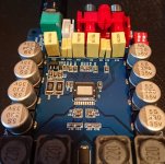
The white paste acts as glue holding the heatsink to the chip. On top, it should be mixed with heat-conducting particles. Some seems just to use silicone which is not sufficient. For a start you have to make tests with the heatsink removed from the chip so you have access.
The white paste should be removed from the chip. It may disturb the chip if it has a bit of conductivity. I use isopropyl alcohol but I normally remove the creamy version. It may be more difficult with the rubber-like type. Use a fine brush. You can eventually try on the heatsink first.
Last edited:
Got it off with nail and clean off with a bit of alcohol on a qtip. Gonna retry it again doubt it will work, but miracles happen. edit nope still no sound. I had another one of these and no issues but i dont have it anymore.
Attachments
Last edited:
This guy has the same problem:
Amplifier Board of TDA7498 Class D Stereo 2x100W - YouTube
Amplifier Board of TDA7498 Class D Stereo 2x100W - YouTube
Thanks for the video link.
There are a few thing you can do to make it work. If that is not sufficient, you have to investigate the board on circuit level and that is not easy.
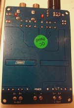
One thing is the small 3.3V voltage regulator near "C10". Could you please tell me what is written on that small voltage regulator?
There are a few thing you can do to make it work. If that is not sufficient, you have to investigate the board on circuit level and that is not easy.
One thing is the small 3.3V voltage regulator near "C10". Could you please tell me what is written on that small voltage regulator?
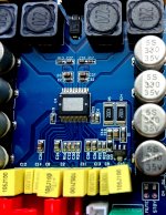
Thanks for the nice photo. Unfortunately I cannot read the text on the small 3-pin voltage regulator. If that voltage regulator has failed, it is very likely that both MUTE and STANDBY are invoked and you have no sound.
This is why I would like you to tell me which type voltage regulator it is. Knowing the type of voltage regulator I can check it in the datasheets and tell you on which pin you should measure the output voltage.
This is why I would like you to tell me which type voltage regulator it is. Knowing the type of voltage regulator I can check it in the datasheets and tell you on which pin you should measure the output voltage.
Holtek HT7536-1, 3.6V, 100mA, Input voltage up to 24V!!
With the cooling tap away from you: GND-left / IN-mid / OUT-right
Datasheet: datasheet HT7536-1
What may be the case is that this small voltage regulator is fed directly from the amp.-chip input voltage. If so, the voltage regulator will soon be over-stressed and fail.
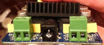
Back-on with your reading glasses! Power ON. Is it possible for you to measure the voltage on the middle pin and the right pin, WITHOUT CAUSING A SHORT-CIRCUIT (not easy)? Other (black) voltmeter probe to supply "-".
With the cooling tap away from you: GND-left / IN-mid / OUT-right
Datasheet: datasheet HT7536-1
What may be the case is that this small voltage regulator is fed directly from the amp.-chip input voltage. If so, the voltage regulator will soon be over-stressed and fail.
Back-on with your reading glasses! Power ON. Is it possible for you to measure the voltage on the middle pin and the right pin, WITHOUT CAUSING A SHORT-CIRCUIT (not easy)? Other (black) voltmeter probe to supply "-".
I actually live in France, on the other side of the big pool of water you can see from NYC. It is a kind offer and I would have appreciated it and even paid the sending costs if it was not so that for less than the sending costs, I can buy a new functional board from Asia and have it delivered in France! On top of that, the customs may charge me for import-fees as they do not care if the board works or not.
I will send you a PM.
I will send you a PM.
Nice amp and dog!
My Dog, a Jack Russel terrier, only shows interest in lots of bass; then he will stand or lay down next to the sub-woofers enjoying his massage.")
Well this one do play piano.
https://twitter.com/i/status/1434387235965657093
- Home
- Amplifiers
- Class D
- My 7498 Class D Amp