Hello All
Looking for the Class D specialists!
At present, I have been working on a Mackie DLM12S sub Amplifier, which the owner told me suddenly became Very Distorted over a couple of days.
Suspecting the 12" Bass Driver, I removed it from the cabinet and test ran it on another amp, and turned out that the driver was good.
Then: on to the Class D amplifier, which in this case is Two Power Amps which are connected to the Driver in Bridge Mode. After Closely measuring everything I could in the Amps and finding nothing amiss, I separated them into Stereo Mode and proceeded to follow the Service Manual Instructions on setting up the Input Oscillators to the correct frequencies. It is here that I ran into something a bit odd; to get these Oscs to set up to the correct 480Khz, (plus or minus 10Khz), I had to rotate both channel trimpots almost a full 2/3 of a turn to get the right frequency. The procedure is that You disable each amp with a Shorting Link while you adjust the other channel. Then You enable both channels and carefully adjust both trimpots to get the 2 channels to they (Mackie) say 'Phase Lock'? How is this possible, because there is no interconnection in that section between both channels, and the oscillators are only one section of an ordinary Opamp?
Anyway, the bottom line to all of this is that after running Each Amp separately with an Audio Signal, and both sounding quite Powerful and Clean, I then reconnected them in Bridge Mode and back on to the Original Bass Driver. But -- no Good -- Still Very Distorted, and it sounds like there are some sort of artifacts in the sound.
Has anyone here experienced this sort of problem? I can Post the Scope waveforms if this will help -- Thanks for all and any help --
With stereo class d amps you can get into a strange interference mode if the clocks are a multiple of each other.
So they usually either set them really close or a long way off to stop beating between the clock frequencies.
Its a while since I designed a stereo amp so my comments might not be quite right.
So they usually either set them really close or a long way off to stop beating between the clock frequencies.
Its a while since I designed a stereo amp so my comments might not be quite right.
Hello
Thanks for all.
In this particular case the clocks are set to exactly the same frequency, eg; 480Khz, and as I explained, there is no way that These 2 clocks can 'Lock' to each other, as they are each only part of an Opamp and are not connected to each other in any way.
Maybe if Mackie had used a Phase Locked Loop, this problem might not exist. The existing Circuit is very simple. I have attached the circuit to help --Thanks for any help --
Attachments
 Moved as requested!
One thing I was curious about, is, how much of the 480Khz signal should you be able to see at the Audio Output Terminals?
In this case, there is over 1 Volt P-Pk. I understood that the filter Network after the Output Devices was suppossed to remove it all?
Thanks for all --
In this case, there is over 1 Volt P-Pk. I understood that the filter Network after the Output Devices was suppossed to remove it all?
Thanks for all --
One thing I was curious about, is, how much of the 480Khz signal should you be able to see at the Audio Output Terminals?
In this case, there is over 1 Volt P-Pk. I understood that the filter Network after the Output Devices was suppossed to remove it all?
Thanks for all --
Its a juggling act with the output filter.
1/ Filter it enough to get rid of the carrier.
2/ Not filter it so much top end of the audio is lost.
Thanks for that --
in this case the 480Khz Clock Frequency is not very stable; Mackie say that You have to set it to 480Khz plus or minus 10Khz, which I did as in the 'Mackie 2' Pdf I attached.
It was actually quite difficult to achieve that, and I followed the instructions given.
Because the Frequency was so wrong at the start, I thought that this might fix the problem, which it did not.
Really, for a Circuit as simple as this, I can not see how the frequency can be that stable -- and how on earth can these 2 lock to each other (as Mackie suggests) when the two are not even connected in any way?
Any comment would be appreciated --
1V pk-pk isn't out of the ordinary. I suspect that the remaining hf that gets past the filters is supposed to be able to affect the triggering of the other side forming a sort of "phase lock" (not really a phase lock, but a similar thing to how old analog TVs used to get their horizontal oscillators synched to the received signal by affecting trip point and timing so they end up tracking).
I'm not a class D expert, but 480kHz seems kind of high (at least it's higher than the dozen or so amps I've seen).
Could it be the power supply collapsing and causing the problem? Maybe put a scope on that and see what it looks like when you're bridged.
I'm not a class D expert, but 480kHz seems kind of high (at least it's higher than the dozen or so amps I've seen).
Could it be the power supply collapsing and causing the problem? Maybe put a scope on that and see what it looks like when you're bridged.
Last edited:
Class D problems
Hello, and thanks --
Good Idea -- I had previously only looked at the supply voltages of Plus and Minus 75 Volts, which looked very stable; but did not check them under load, as the ESR of all the electros looked to be good.
Strange thing though, is that when separated into two amps, each one sounded quite powerful and clean. Only seems to be when You put them back into bridge mode that the problem exists.
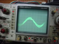
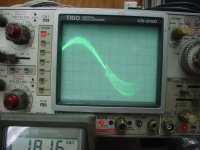
There is something in the Bridge Output Waveform that I don't quite understand --
This was taken with an 80 Hz input, (where it seems the filtering is centred at) via the onboard preamp.
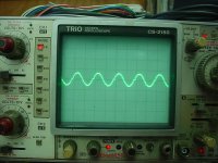
I have attached a shot of the scope view; the second shot is the RF signal as viewed at the Output Terminals -- Doesn't look that good
Thanks for all --
Hello, and thanks --
Good Idea -- I had previously only looked at the supply voltages of Plus and Minus 75 Volts, which looked very stable; but did not check them under load, as the ESR of all the electros looked to be good.
Strange thing though, is that when separated into two amps, each one sounded quite powerful and clean. Only seems to be when You put them back into bridge mode that the problem exists.
There is something in the Bridge Output Waveform that I don't quite understand --
This was taken with an 80 Hz input, (where it seems the filtering is centred at) via the onboard preamp.
I have attached a shot of the scope view; the second shot is the RF signal as viewed at the Output Terminals -- Doesn't look that good
Thanks for all --
Attachments
Hello
Thanks for all.
In this particular case the clocks are set to exactly the same frequency, eg; 480Khz, and as I explained, there is no way that These 2 clocks can 'Lock' to each other, as they are each only part of an Opamp and are not connected to each other in any way.
Maybe if Mackie had used a Phase Locked Loop, this problem might not exist. The existing Circuit is very simple. I have attached the circuit to help --Thanks for any help --
can you provide full schematic ?
Hello
Here is the Full Schematic -- Supply Rails are Plus and Minus 75 volts.
The Power Supply is of course Switch Mode -- Would You also like to see the Schematic of that?
Thanks for all --
Yes please I like to see Schematic Power Supply too, please provide
Hello
There are 2 Switch Mode Power Supplies. Main and Auxiliary --
Attached are both --
Thanks, and Best Regards
Telnet100
thanks
Problem fixed, Bridge mode working ?
Hello
The Bridge Mode is working, but only with limited Power Output and Distorted Sound.
I was waiting from some more advice on it. There are two pages of stuff about it here.
Class D is something that I do not know much about; only the principle of operation --
This is because up until now, I have only been involved with the repair of analogue amps and so forth. This current repair belongs to a Band Member who relies on His gear to make a living, and so I need to get this thing sorted.
Thanks for any help, and best regards --
Hello Again --
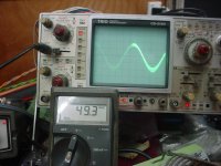
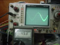
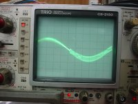
I decided to Drive the Output into my Fan cooled 8 Ohm Resistor Stack, and here are the results. I am Unable to drive it into clipping, but I suspect that is due to the fact that there is a Soft Limiting Stage in the front end.
The Output Waveform at 80 Hz does look clean, but with quite a bit of residual RF component. The Last Two were taken with a 100Hz input, but at a lower Power Level.
What is the artifact that you are able to see on the signal? -- Do these results appear to show a well functioning Class Bridge Amplifier?
The Measured Output on the 'scope is 90 Volts P-P, which, divided by 2 to get peak, and then Multiplied by 0.707 to get RMS, is 31.8 Volts. Divide that by the 8 Ohm Load Resistor Value, and You get 3.97 Amps RMS. Multiply 3.97A x 31.8 Volts and the result becomes 126 Watts RMS Undistorted. Where on Earth can Mackie get an Output Claim of 1000 Watts? - or am I missing something here?
Attachments
can you drive the load just with the +/- power supply and measure V and A at 8 ohms? so you can proof the PS is OK and the fault is at the amp section? If that is OK, I´d go to next idea:
Seems like there is a problem when going over zero in the negative half wave. This might sound OK in SE but will distort bridged for sure. So one half of your two amps has a problem.
Seems like there is a problem when going over zero in the negative half wave. This might sound OK in SE but will distort bridged for sure. So one half of your two amps has a problem.
Hello
Thanks for that --
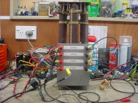
So what You mean: is to place an 8 Ohm resistor across each of the Plus and Minus Power Supply Rails and measure the V and I? I have some pretty big Fan Cooled Resistors that can cope with this -- It Runs Plus and Minus 75 Volts, so I guess that I'll be looking for at least 9.37 Amps Output -- Agreed? Attached is a shot of what I mean by big resistors --
Awaiting your helpful comments --
Thanks for that --
So what You mean: is to place an 8 Ohm resistor across each of the Plus and Minus Power Supply Rails and measure the V and I? I have some pretty big Fan Cooled Resistors that can cope with this -- It Runs Plus and Minus 75 Volts, so I guess that I'll be looking for at least 9.37 Amps Output -- Agreed? Attached is a shot of what I mean by big resistors --
Awaiting your helpful comments --
Attachments
- Status
- This old topic is closed. If you want to reopen this topic, contact a moderator using the "Report Post" button.
- Home
- Amplifiers
- Class D
- Class D Questions