Thanks guys.
I think I will desolder the caps as my soldering is not that delicate and solder on some larger caps donated from this broken amp board. I think they are compatible and will make the process a whole lot less rage inducing.
Now that the gain has been lowered the datasheet recommends changing the input cap value and as per the example circuit with 60k input it suggests 0.15uf. Is this the case? I believe the input caps at the moment are 1uf. Can anyone clarify please?
As for the 'mute' pin? Well, that just goes to voltage as per the example circuit in the datasheet. I should have realised.
btw..
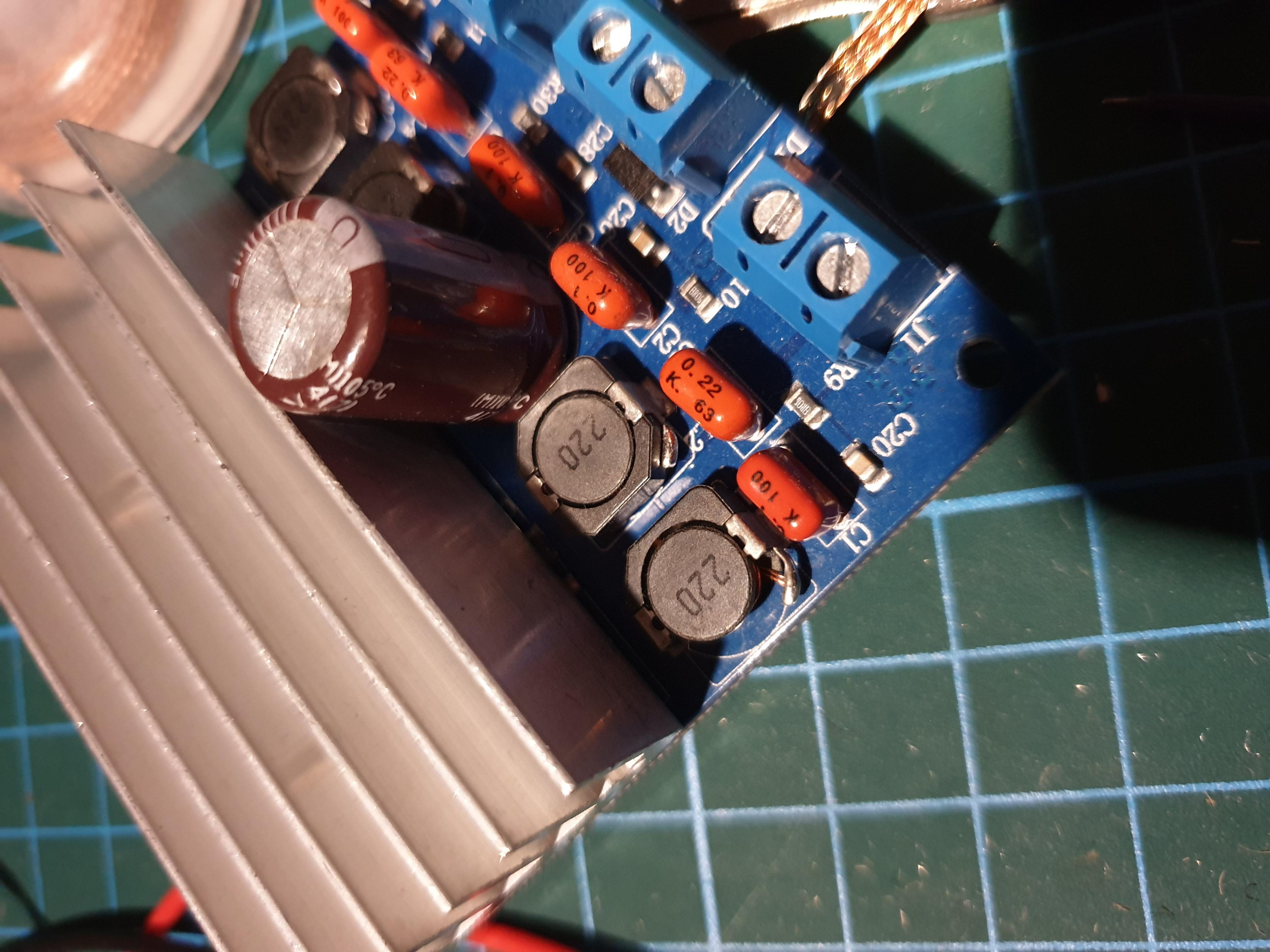
what happend to this board??? TDA7498?
Thanks Chris! I am pretty certain the cap is an OK type, it came from another class D board and is the same ChongX brand as the smaller one that came off the TPA3110 board. However, I will try and measure it tonight. Can I do this with a cheap multimeter (which is all I have)?
I am using a 20v / 3a laptop PSU, I should haven mentioned this earlier! I have a few questions about this that I will post in a minute.
The TDA7492 is one of a pair I ordered from china and one turned up with a chipped ferrite case to an inductor. The seller refunded me so I have been treating it as a little parts bin! However, the other one that works sounds great! That is next on my list of amps to try and get the best out of!
Thanks for the help so far guys, I'm enjoying these challenges!
Let's talk power...
Currently I am using a 20v 3a laptop power supply with the 1000uf reserve capacitor. I think this is ample for this amp now. However, the on board linear regulator is running super hot as it has a huge voltage to step down to 5v for the DSP and Bluetooth boards.
I have read that maybe the TPA3110D2 should be run at a lower voltage anyway?
This gives me a couple of options:
1. Buy a different power supply at a lower voltage. I was thinking around 15v/3a. Would this greatly effect power output from the amp?
2. Change the on board linear reg to a 12v version but then I fear I will mess with the balance of the board circuit.
3. Keep the 20v supply and use an off board linear regulator with bigger heat sinks to first step the voltage down to 12v (which the DSP will accept) then a further linear regulator from the 12v supply down to the 5v needed for the bluetooth board. This way does sound a little wasteful of energy and I worry I'll be leaching away a lot of power that will just be burned off, so to speak.
Let's talk USB power...
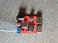
In this build I want to include two USB charging points and I bought this board to do so and it will take power directly from the PSU. I have tried this and when a phone is charging (but unconnected from the amp in any other way) there is high-pitched noise. How can I avoid this? Would ferrite on the power cables running to the board help?
The board has 1A and 2A charging sockets, if they were to both be used would the sound suffer? Are there any measures to prevent this?
As ever, any thoughts are greatly appreciated!
Let's talk power...
Currently I am using a 20v 3a laptop power supply with the 1000uf reserve capacitor. I think this is ample for this amp now. However, the on board linear regulator is running super hot as it has a huge voltage to step down to 5v for the DSP and Bluetooth boards.
I have read that maybe the TPA3110D2 should be run at a lower voltage anyway?
This gives me a couple of options:
1. Buy a different power supply at a lower voltage. I was thinking around 15v/3a. Would this greatly effect power output from the amp?
2. Change the on board linear reg to a 12v version but then I fear I will mess with the balance of the board circuit.
3. Keep the 20v supply and use an off board linear regulator with bigger heat sinks to first step the voltage down to 12v (which the DSP will accept) then a further linear regulator from the 12v supply down to the 5v needed for the bluetooth board. This way does sound a little wasteful of energy and I worry I'll be leaching away a lot of power that will just be burned off, so to speak.
Let's talk USB power...
In this build I want to include two USB charging points and I bought this board to do so and it will take power directly from the PSU. I have tried this and when a phone is charging (but unconnected from the amp in any other way) there is high-pitched noise. How can I avoid this? Would ferrite on the power cables running to the board help?
The board has 1A and 2A charging sockets, if they were to both be used would the sound suffer? Are there any measures to prevent this?
As ever, any thoughts are greatly appreciated!
Attachments
Hi
Let's talk power...
Currently I am using a 20v 3a laptop power supply with the 1000uf reserve capacitor. I think this is ample for this amp now. However, the on board linear regulator is running super hot as it has a huge voltage to step down to 5v for the DSP and Bluetooth boards.
I have read that maybe the TPA3110D2 should be run at a lower voltage anyway?
yes it should work down to 8V
This gives me a couple of options:
1. Buy a different power supply at a lower voltage. I was thinking around 15v/3a. Would this greatly effect power output from the amp?
Pmax = Upp^2 / R => yes you will get less power, ..not good") ...but try it...the needed voltage drop for the regulator is about 2-3V so it would fit (8V-3V = 2V for DSP + BT
...but try it...the needed voltage drop for the regulator is about 2-3V so it would fit (8V-3V = 2V for DSP + BT
2. Change the on board linear reg to a 12v version but then I fear I will mess with the balance of the board circuit.
no keep that board as it is..its working
3. Keep the 20v supply and use an off board linear regulator with bigger heat sinks to first step the voltage down to 12v (which the DSP will accept) then a further linear regulator from the 12v supply down to the 5v needed for the bluetooth board. This way does sound a little wasteful of energy and I worry I'll be leaching away a lot of power that will just be burned off, so to speak.
yes this could be a solution - you can use a buck regulator, like the LM2596...there are a lot of cheap small pcb ...
chris
Let's talk power...
Currently I am using a 20v 3a laptop power supply with the 1000uf reserve capacitor. I think this is ample for this amp now. However, the on board linear regulator is running super hot as it has a huge voltage to step down to 5v for the DSP and Bluetooth boards.
I have read that maybe the TPA3110D2 should be run at a lower voltage anyway?
yes it should work down to 8V
This gives me a couple of options:
1. Buy a different power supply at a lower voltage. I was thinking around 15v/3a. Would this greatly effect power output from the amp?
Pmax = Upp^2 / R => yes you will get less power, ..not good
...but try it...the needed voltage drop for the regulator is about 2-3V so it would fit (8V-3V = 2V for DSP + BT2. Change the on board linear reg to a 12v version but then I fear I will mess with the balance of the board circuit.
no keep that board as it is..its working
3. Keep the 20v supply and use an off board linear regulator with bigger heat sinks to first step the voltage down to 12v (which the DSP will accept) then a further linear regulator from the 12v supply down to the 5v needed for the bluetooth board. This way does sound a little wasteful of energy and I worry I'll be leaching away a lot of power that will just be burned off, so to speak.
yes this could be a solution - you can use a buck regulator, like the LM2596...there are a lot of cheap small pcb ...
chris
Hi graham
Let's talk USB power...
In this build I want to include two USB charging points and I bought this board to do so and it will take power directly from the PSU. I have tried this and when a phone is charging (but unconnected from the amp in any other way) there is high-pitched noise. How can I avoid this? Would ferrite on the power cables running to the board help?
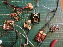
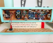
on the pic it looks like that you use the same cables like the amp speakers output (if i look at the pics before)- the cables have the same color!!
i hope not
if i understand you. the amp and the USB charger are just connected on the same psu. no other connection are done?
so its sound like you get something over the rails? to the speakers?
The board has 1A and 2A charging sockets, if they were to both be used would the sound suffer? Are there any measures to prevent this?
no idea
Let's talk USB power...
In this build I want to include two USB charging points and I bought this board to do so and it will take power directly from the PSU. I have tried this and when a phone is charging (but unconnected from the amp in any other way) there is high-pitched noise. How can I avoid this? Would ferrite on the power cables running to the board help?
on the pic it looks like that you use the same cables like the amp speakers output (if i look at the pics before)- the cables have the same color!!
i hope not
if i understand you. the amp and the USB charger are just connected on the same psu. no other connection are done?
so its sound like you get something over the rails? to the speakers?
The board has 1A and 2A charging sockets, if they were to both be used would the sound suffer? Are there any measures to prevent this?
no idea
Thanks for the input!
Yes, don't worry, it is a different type of cable being used - a multi strand type I used very quickly to test.
Yes, it is a noise that can only come from the power lines. I am really unsure how to research solving this. My stab in the dark was ferrite?
I have a few LM317 boards on the way so will experiment with chaining them to get the correct voltages. I have ordered some larger heat sinks as well as the ones that come with it look wimpy and get hot.
OK, some further thoughts and questions:
In respect to capacitors going in to the board via the power I have read that the diode that protects against incorrect power polarity effects bass response. Should I remove this? Of course I can try and see but I am will it have a detrimental effect to the board?
When making a reserve capacitor bank should I remove the large electrolytic from the board and solder in a connection to an outboard bank of paralleled capacitors or should I just run the bank of caps straight in-line to the positive power input? It is my understanding that series capacitors halve the capacitance which would be the case if the resevoir bank was in-line straight to the positive board connection.
I feel my test of going from 470uf to 1,000uf was not big enough of a jump to have any meaningful result so I want to try somewhere around 5,000-10,000uf if I have the caps available.
Also, something that puzzles me. Should the reservoir capacitor be closer to the board/chip? I have seen other projects where these are separate from the the main amp board. Can I populate a separate PCB for this purpose and keep it away from the board?
I have some prototype board arriving tomorrow and it looks like it will rain all day so I will be kept busy!
As always any thoughts are appreciated!
(and please let me know if any of my descriptions are confusing!)
test always with a resistive load to setup your voltageThanks for the input!
Yes, don't worry, it is a different type of cable being used - a multi strand type I used very quickly to test.
Yes, it is a noise that can only come from the power lines. I am really unsure how to research solving this. My stab in the dark was ferrite?
sorry but i have no idea ...here...
I have a few LM317 boards on the way so will experiment with chaining them to get the correct voltages. I have ordered some larger heat sinks as well as the ones that come with it look wimpy and get hot.
OK, some further thoughts and questions:
In respect to capacitors going in to the board via the power I have read that the diode that protects against incorrect power polarity effects bass response. Should I remove this? Of course I can try and see but I am will it have a detrimental effect to the board?
keep it...the 0,3V drop you will not really "need"
When making a reserve capacitor bank should I remove the large electrolytic from the board and solder in a connection to an outboard bank of paralleled capacitors or should I just run the bank of caps straight in-line to the positive power input? It is my understanding that series capacitors halve the capacitance which would be the case if the resevoir bank was in-line straight to the positive board connection.
no no no....capacitance is getting double if you use 2 types of same caps in parrallel! .keep the caps as near as possible to the chip. if you want to put some extra caps there so solder it on the pcb underside or try to solder to smaller caps at the same place....not so easy because your board is tiny.......use a low ESR/ESR caps about 1000-2000µF and its good...the rest sould do a strong psu -- watch the polarity
I feel my test of going from 470uf to 1,000uf was not big enough of a jump to have any meaningful result so I want to try somewhere around 5,000-10,000uf if I have the caps available.
no...no need. i never had bass problems in all my amps what i mod....maybe my open baffle are superior at bass response
Also, something that puzzles me. Should the reservoir capacitor be closer to the board/chip? I have seen other projects where these are separate from the the main amp board. Can I populate a separate PCB for this purpose and keep it away from the board?
I have some prototype board arriving tomorrow and it looks like it will rain all day so I will be kept busy!
As always any thoughts are appreciated!
(and please let me know if any of my descriptions are confusing!)
Don't expect much from adding some more caps.
First, check how much capacitance your audio coupling caps have, then calculate the -3dB frequency together with the input impedance of the amp (which is gain related).
At 20dB gain, input impedance is 60k. Together with those 100nF coupling caps, your -3dB frequency calculates to about 26Hz. If your source also provides output coupling caps, this is even less so -3dB frequency will rise.
Change the 100nF caps for 1uF and listen.
Last edited:
Thanks guys!
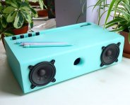
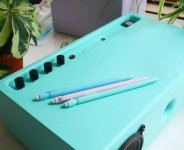
This is beginning to take shape rather nicely. I have a few issues with the DSP function at the moment and the USB charging noise is a mystery to me (ferrite will be given a go!?) but it's a great little rig so far.
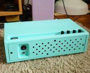
Can anyone advise on what type of internal fuses I should use for safety, if at all, please? It is all powered from a 3.5a 20v SMPS.
This is beginning to take shape rather nicely. I have a few issues with the DSP function at the moment and the USB charging noise is a mystery to me (ferrite will be given a go!?) but it's a great little rig so far.
Can anyone advise on what type of internal fuses I should use for safety, if at all, please? It is all powered from a 3.5a 20v SMPS.
Attachments
So you haven't changed the coupling caps yet?
5x20mm glas-fuses would come in mind as there are wired holder available. For the DSP and electronics i'd go for "fast blow" type at rougly 2-3x times the current the board usually pulls. The amp board is fine with 3A "medium blow".
5x20mm glas-fuses would come in mind as there are wired holder available. For the DSP and electronics i'd go for "fast blow" type at rougly 2-3x times the current the board usually pulls. The amp board is fine with 3A "medium blow".
Hi all!
Apologies for this thread being inactive for such a long while. Getting married took over for a bit.
I got straight back in to this and switched it up to use a TPA3118 board instead as I felt the TPA3110 felt a bit strained. Maybe it was the board, maybe it was my ears, but I saw no reason not to go with an already more powerful chip instead.
Thank you all so much for the help, I got it running really well with all your advice here and my friend loves it!
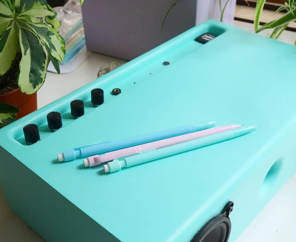
I used a nice CSRA64215 board which allowed me a microphone as well. The ADAU1701 gives flattness EQ plus bass and treble. I put heatsinks on the back of the TPA3118 board too. I added a USB quick charge board as well!
Bluetooth range isn't great but I wonder if these boards ever have good range to begin with?
On to the next project!


Apologies for this thread being inactive for such a long while. Getting married took over for a bit.
I got straight back in to this and switched it up to use a TPA3118 board instead as I felt the TPA3110 felt a bit strained. Maybe it was the board, maybe it was my ears, but I saw no reason not to go with an already more powerful chip instead.
Thank you all so much for the help, I got it running really well with all your advice here and my friend loves it!
I used a nice CSRA64215 board which allowed me a microphone as well. The ADAU1701 gives flattness EQ plus bass and treble. I put heatsinks on the back of the TPA3118 board too. I added a USB quick charge board as well!
Bluetooth range isn't great but I wonder if these boards ever have good range to begin with?
On to the next project!
Attachments
Hi Graham,
First, congratulations with your marriage. You are right, it is well seen if you at least take part on the wedding evening of your own marriage. Spouses start sulking if you are seen with a soldering iron in your hand that day.
The outcome looks really good. You are a good craftsman and the color is difficult to find elsewhere. You were clever to use separate Bluetooth and amplifier boards. It is tempting to buy an "all on one board" but then you are stuck with that combination and cannot upgrade for instance the Bluetooth board when a version with extended performance appears on the market. Also fault-finding on a single board is difficult.
On to the next project - that's the DIY spirit.
Last edited:
Hi Graham,
First, congratulations with your marriage. You are right, it is well seen if you at least take part on the wedding evening of your own marriage. Spouses start sulking if you are seen with a soldering iron in your hand that day.
The outcome looks really good. You are a good craftsman and the color is difficult to find elsewhere. You were clever to use separate Bluetooth and amplifier boards. It is tempting to buy an "all on one board" but then you are stuck with that combination and cannot upgrade for instance the Bluetooth board when a version with extended performance appears on the market. Also fault-finding on a single board is difficult.
On to the next project - that's the DIY spirit.
Thanks man! I was given strict instructions t not get carried away fiddling with the 4k Turbosound system I rented for our disco. I even got to DJ!
Yes, I have a 3 BT+amp boards and all of them are useless, perhaps I picked bad ones. Next I would like to use the balanced out of a BT board straight to DSP then amp in the same fashion.
I think this mint color is VERY BRITISH and nowhere else on the world available.
(no pun intended!)
My friend picked the colour but I always do stuff in pastels!

Hi Graham
You are married...Congratulations!
@DIY
your power box with BT is nice. structured and good thinking...Well done!
chris
DIY never stop
Cheers man! Thanks for your help on this one!
- Status
- This old topic is closed. If you want to reopen this topic, contact a moderator using the "Report Post" button.
- Home
- Amplifiers
- Class D
- TPA3110d2 BT Board Fixes?