It is a heat spreader, not a heat sink.
Poor what ever it is.
Poor what ever it is.
Do you mean that Hypex is poor ?
Do you mean that Hypex is poor ?
lol no the heat sink.
I think you trolling here. You were just told its not a heat-sink whats wrong with you?lol no the heat sink.
I think you trolling here. You were just told its not a heat-sink whats wrong with you?
I don't agree, it is a heat sink.
Its meant to get rid of heat so by definition it is a heat sink.
No fins means inefficient operation so bad or cheap design.
The modules seems well designed and reliable but there is 3.6w to dissipate, even at idle.
You should perform a temperature measurement of the small white coated PCB after 2 hours at idle at 25°C.
Yes it was white, the thermal design looks like a flirt with the thermal limit.

This is an older generation module by the looks for it, later modules use a different potting compound, later modules use black tar compound for this very reason.
I don't agree, it is a heat sink.
Its meant to get rid of heat so by definition it is a heat sink.
No fins means inefficient operation so bad or cheap design.
With that logic, the metal case of a TO-220 package is a heat-sink to.
it sounds more like difficultly accepting terminology over application.
It acts an a mechanical damper for the PCB as well.
Last edited:
With that logic, the metal case of a TO-220 package is a heat-sink to.
it sounds more like difficultly accepting terminology over application.
I have been doing it for 40 years so cant be far wrong !
A heat spreader transfers energy as heat from a hotter source to a colder heat sink or heat exchanger. There are two thermodynamic types, passive and active.
Heat spreader - Wikipedia
Heat spreader - Wikipedia
A heat spreader transfers energy as heat from a hotter source to a colder heat sink or heat exchanger. There are two thermodynamic types, passive and active.
Heat spreader - Wikipedia
But it does it inefficiently if its just a block of metal.
It needs to have fins to increase the surface area to the air.
Sounds like a cheap and nasty answer to a heatsink.
The modules seems well designed and reliable but there is 3.6w to dissipate, even at idle.
You should perform a temperature measurement of the small white coated PCB after 2 hours at idle at 25°C.
Yes it was white, the thermal design looks like a flirt with the thermal limit.
wow. all of that 3.6W at idle?? how can one handle that?

I'm used to 60-300W at idle.
But it does it inefficiently if its just a block of metal.
It needs to have fins to increase the surface area to the air.
Sounds like a cheap and nasty answer to a heatsink.
It is ment to be boltet to a heatsink.
wow. all of that 3.6W at idle?? how can one handle that?
I'm used to 60-300W at idle.
In the class D world, modern multi channel amps are able of less than 1W.
Now in my country we have smart electric meters we are constantly spied by the electricity company, class a amplifiers will be prohibited.
I don't agree, it is a heat sink.
Its meant to get rid of heat so by definition it is a heat sink.
No fins means inefficient operation so bad or cheap design.
The aluminium block in the ucd400 is designed to be bolted to a heatsink, it's there to carry the heat from the power devices to a sufficient cooling system. It works absolutely fine but I have no idea if it would be sufficient if the amp was driven for full dissipation.
The modules seems well designed and reliable but there is 3.6w to dissipate, even at idle.
You should perform a temperature measurement of the small white coated PCB after 2 hours at idle at 25°C.
3.6 watts? Mine always dissipated far more than 3.6 watts. The datasheet says 8 watts when running on 65V rails.
It's not the heating that is the problem. It's the builders lack of cooling.
My UcD amps never get hotter than about 5 degrees over roomtemp.
Well I had my pair bolted to a large, completely overkill, heat sink from another case/project I had lying around. The reliability was challenged when I dropped a screw driver and it fell onto the banana plugs of one output channel. This shorted the output and the amplifier exploded. This should not have happened, the protection circuitry is there to prevent this exact thing from happening.


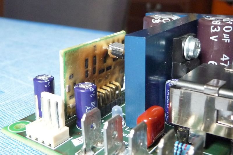
NAD has been more cautious with its customized Hypex UCD.
The thermal coupling between the two p14nf12fp was better with the T shaped heatspreader and the potted inductors are also better on the module.
The NAD desing looks like a jump in the past, moreover the heatsink is undersized for 20W.
Last edited:
5th, what did Hypex say about that failure?
I didn't contact them. I replaced the blown MOSFET and the amp jumped back into life. Then, for some completely unknown reason, the other channel exploded. It took a while for me to get that one back going. Then reliability hit the fan and now both are dead. I can't be bothered with them any more. Too much effort and time wasted. These are not easy amplifiers to trouble shoot due to their completely discrete design, I will be moving on to something else.
High power class D isn't my forte so I went with the Hypex modules specifically to relieve myself of a headache in assuming they'd be completely reliable. I'd have been better building something of my own from the start.
Last edited:
Too much effort and time wasted. These are not easy amplifiers to trouble shoot due to their completely discrete design, I will be moving on to something else.
Could be all sorts of reasons for blown mosfets.
1/ Poor decoupling on the rails letting noise spikes through causing transistor breakdown voltage to be reached.
2/ Shoot through due to insufficient dead time.
3/ Over heating due to poor heat sink or shoot through.
- Home
- Amplifiers
- Class D
- Hypex module reliability (UCD)