I decided to start this after I bought a cheap tda7492 board that sounds not so good, and the info on modding it and component selection was scattered all around, so I picked it up and compiled the usefull knowledge here.
Please, read all before doing anything to your board, and specially go trough step 4 before changing components at the output.
All that info apply to Class D without feedback, please refer to the datasheet of your module and make sure you dont change anything out of specs. The most relevant references are here:
Trevor's blog little class D tuto
Texas Instruments notes
Texas's output filter calculator
EETimes article
Maxim Itegrated aaplication note on types of caps for audio
Your module/chip datasheet (this one is your job, go find it)
First, there may be 4 probable fonts of unwanted hum, hiss or noise in your board
1 bad quality components
2 bad signal input
3 bad ground connections
4 bad output filter
1 Lets start by the most common, the nightmare of audiophiles, bad quality capacitors!
These little guys can mess with everything you want, on the maxim note they explain that. TL/DR chinese use cheap X7R ceramic caps, cheap and small, but they act like a piezo element, when voltage is applied they deform, change capacitance, and resonate with the circuit, you don't want nothing resonating, you just want you audio signal.
If you see small light brown smd caps they're probably X7R, if they are on audio paths, it'd be good to change for some multilayer polymer dieletric (polyester, mylar, polycarbonate, polyestirene) or to NP0 caps, since they dont give a **** about voltage, temperature or current variation, and they have reasonably low esr. DON'T use electrolitic caps here, they have HIGH esr, so they are most suited for storing energy than signal conitioning.
2 Second, if you have bad audio input, you'll have bad audio output, amps don't do magic. Make sure you have a matching input, if your amp is single ended, use single ended signal, and so on.
Make sure you have good coupling caps at your input. Coupling caps are in series with the input conector and the chip input, if they are X7R, make sure to change them, the datasheet of the board or the chip can suggest good values to use.
If you have a buffer(little amp with no gain, in level=out level, used to match impedance) make sure that it's a good one by reading the chip datasheet, if you're not sure, ask for help at the forum on if its ok to leave and if not how to mod it.
When you can, use differential input, it will sound better since it dont have ground connection, gnd usually carry heavy noise caused by the fast switching output.
3 Here we are, this one is a bit complicated, please do some research on "ground plane pcb desing" and "star connected ground".
Since everything that's referenced to ground have to be connected to it, including the output supply, they will probably share the same noise, and output stage on Class D cause a hell of a noise, so watch your connections carefully, this can be mitigated by some clever path designing, but I'm not the most suited to teach ou this.
4 The baddest of all, poorly designed output filter.
The output filter work by getting rid of the switching carrier frequency, so you get only the audio that was superimposed at the modulation stage. A filter is an association of capacitors and inductors/coils, and think what also have a coil inside? Yes, your speaker. So an output filter need to be designed to match the speaker you will use. It can be done with some room for change, like design it for 5 ohms, so it work with both 4 ohms and 6 ohms.
But, chinese manufacturers usually use what they want, and usually they want you to use 8 ohms or higher.
Output filters have a quality factor, that tells you how good it is filtering. For a given filter, you'll have a linear response till the cut frequency, that for class D is usually 22-40 KHz, and then a sudden step down in response. If you change the speaker, you change a bit of the filter inductance, so you change your filter caracteristics. Usually, by increasing speaker impedance you increase qualitiy factor, good right?
High quality factor will give you a stepper response at the cut out frequency, but will give a huge spike right below it, so if your filter has a high Q, and cut frequency at 22KHz, you will see harsh threbble cause of the huge spike near cut out frequency.
Lower Q will give you a smooth roll off, that happen by reducing speaker's impedance, so youl get poor performance at high frequencies.
Texas Instrument has given us an excel sheet that do all the heavy calculation, just look at you board and insert the values here, then see what happens, and play with them a bit.
Here's mine stock components calculations:
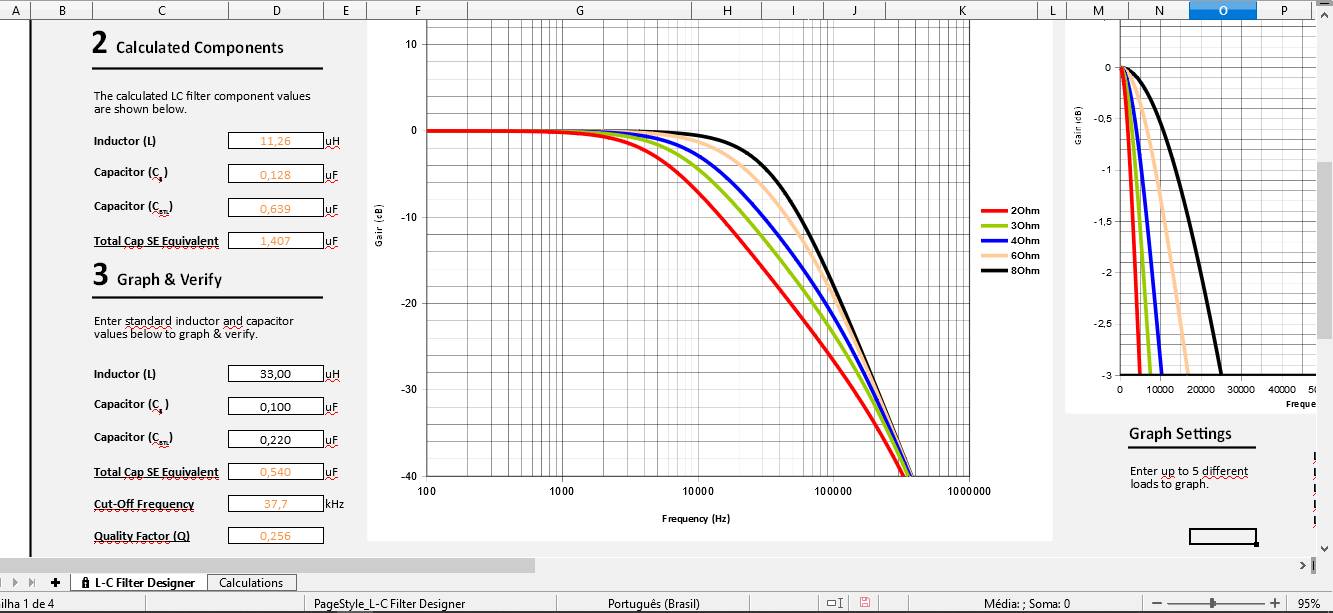 Interesting to note: Even if these boards should perform poorly with treble at lower impedances, the effects of X7R caps give it a nasty harsh sound.
After some tweaking for my 4ohm speaker:
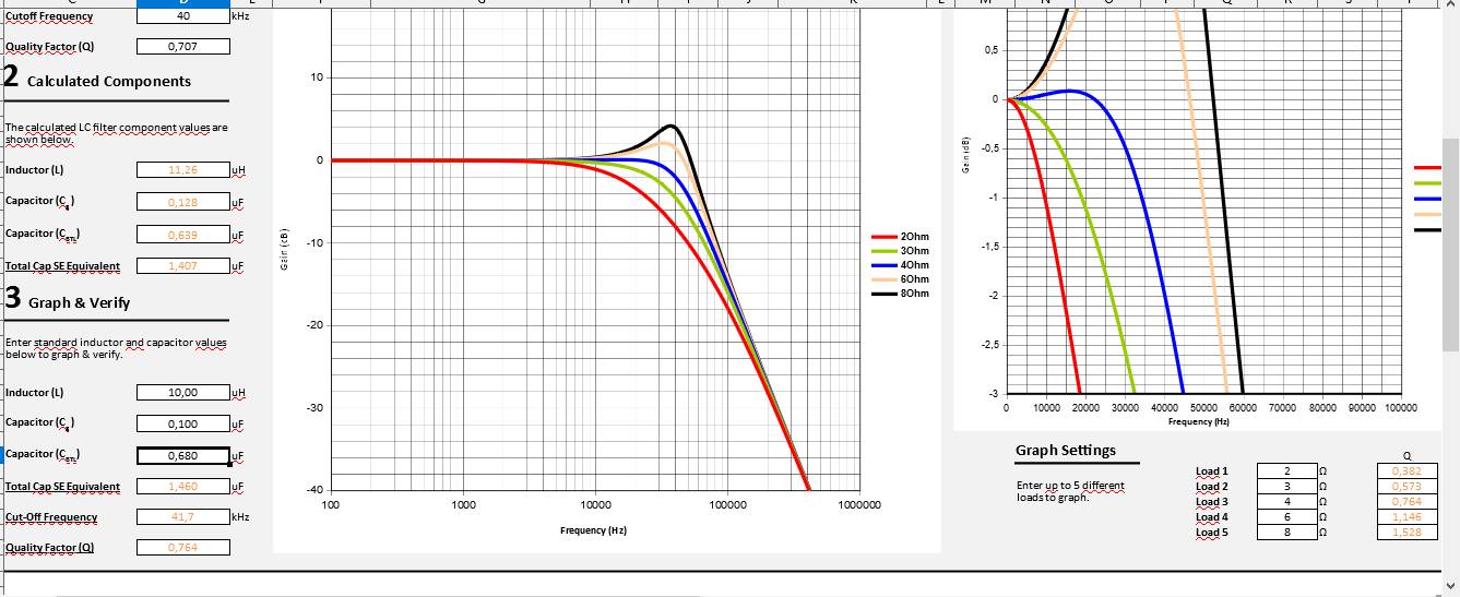
Besides all that, they tend to use the cheapest coils and caps they have. The caps where already adressed, but the inductors play a key role here.
The inductor have a max current at wich they still work as an inductor, after it the losses increase at an incredible rate. So if you want to dry out every single watt of your amp, take in consideration the DC current that can pass trough the coil, so use a coil that can endure that. A rule of thumb is that more current = denser magnetic field, and core material have a limited capacity of magnetic fiel for a given core area(pls dont correct me on these terms, they're for sake of understanding, not for technical specs), so if you want a bigger current, use a coil with bigger core area, and the same value of inductance.
Core material should be ferrite/ceramic, since we're talking abou high frequency, 250-400Khz.
After you've checked all that above, you can look at your board and try to extract the schematic of the amp, principally the filter, and compare it to the seggested topology of the datasheet, if you see some diversion, it'd be good to correct it, like, some boards lack a snubber, a device that supresses transients and prevent your amp from being a radio antenna, it is a resistor in series with a little cap, conected between the amp outputs, before the filter.
I, like most of you, dont have a setup for complex measurements here, but if you've done it right, now you should have a good sound board, some people, like Trevor, even use those on HiFi setups.
Please, read all before doing anything to your board, and specially go trough step 4 before changing components at the output.
All that info apply to Class D without feedback, please refer to the datasheet of your module and make sure you dont change anything out of specs. The most relevant references are here:
Trevor's blog little class D tuto
Texas Instruments notes
Texas's output filter calculator
EETimes article
Maxim Itegrated aaplication note on types of caps for audio
Your module/chip datasheet (this one is your job, go find it)
First, there may be 4 probable fonts of unwanted hum, hiss or noise in your board
1 bad quality components
2 bad signal input
3 bad ground connections
4 bad output filter
1 Lets start by the most common, the nightmare of audiophiles, bad quality capacitors!
These little guys can mess with everything you want, on the maxim note they explain that. TL/DR chinese use cheap X7R ceramic caps, cheap and small, but they act like a piezo element, when voltage is applied they deform, change capacitance, and resonate with the circuit, you don't want nothing resonating, you just want you audio signal.
If you see small light brown smd caps they're probably X7R, if they are on audio paths, it'd be good to change for some multilayer polymer dieletric (polyester, mylar, polycarbonate, polyestirene) or to NP0 caps, since they dont give a **** about voltage, temperature or current variation, and they have reasonably low esr. DON'T use electrolitic caps here, they have HIGH esr, so they are most suited for storing energy than signal conitioning.
2 Second, if you have bad audio input, you'll have bad audio output, amps don't do magic. Make sure you have a matching input, if your amp is single ended, use single ended signal, and so on.
Make sure you have good coupling caps at your input. Coupling caps are in series with the input conector and the chip input, if they are X7R, make sure to change them, the datasheet of the board or the chip can suggest good values to use.
If you have a buffer(little amp with no gain, in level=out level, used to match impedance) make sure that it's a good one by reading the chip datasheet, if you're not sure, ask for help at the forum on if its ok to leave and if not how to mod it.
When you can, use differential input, it will sound better since it dont have ground connection, gnd usually carry heavy noise caused by the fast switching output.
3 Here we are, this one is a bit complicated, please do some research on "ground plane pcb desing" and "star connected ground".
Since everything that's referenced to ground have to be connected to it, including the output supply, they will probably share the same noise, and output stage on Class D cause a hell of a noise, so watch your connections carefully, this can be mitigated by some clever path designing, but I'm not the most suited to teach ou this.
4 The baddest of all, poorly designed output filter.
The output filter work by getting rid of the switching carrier frequency, so you get only the audio that was superimposed at the modulation stage. A filter is an association of capacitors and inductors/coils, and think what also have a coil inside? Yes, your speaker. So an output filter need to be designed to match the speaker you will use. It can be done with some room for change, like design it for 5 ohms, so it work with both 4 ohms and 6 ohms.
But, chinese manufacturers usually use what they want, and usually they want you to use 8 ohms or higher.
Output filters have a quality factor, that tells you how good it is filtering. For a given filter, you'll have a linear response till the cut frequency, that for class D is usually 22-40 KHz, and then a sudden step down in response. If you change the speaker, you change a bit of the filter inductance, so you change your filter caracteristics. Usually, by increasing speaker impedance you increase qualitiy factor, good right?
High quality factor will give you a stepper response at the cut out frequency, but will give a huge spike right below it, so if your filter has a high Q, and cut frequency at 22KHz, you will see harsh threbble cause of the huge spike near cut out frequency.
Lower Q will give you a smooth roll off, that happen by reducing speaker's impedance, so youl get poor performance at high frequencies.
Texas Instrument has given us an excel sheet that do all the heavy calculation, just look at you board and insert the values here, then see what happens, and play with them a bit.
Here's mine stock components calculations:
After some tweaking for my 4ohm speaker:
Besides all that, they tend to use the cheapest coils and caps they have. The caps where already adressed, but the inductors play a key role here.
The inductor have a max current at wich they still work as an inductor, after it the losses increase at an incredible rate. So if you want to dry out every single watt of your amp, take in consideration the DC current that can pass trough the coil, so use a coil that can endure that. A rule of thumb is that more current = denser magnetic field, and core material have a limited capacity of magnetic fiel for a given core area(pls dont correct me on these terms, they're for sake of understanding, not for technical specs), so if you want a bigger current, use a coil with bigger core area, and the same value of inductance.
Core material should be ferrite/ceramic, since we're talking abou high frequency, 250-400Khz.
After you've checked all that above, you can look at your board and try to extract the schematic of the amp, principally the filter, and compare it to the seggested topology of the datasheet, if you see some diversion, it'd be good to correct it, like, some boards lack a snubber, a device that supresses transients and prevent your amp from being a radio antenna, it is a resistor in series with a little cap, conected between the amp outputs, before the filter.
I, like most of you, dont have a setup for complex measurements here, but if you've done it right, now you should have a good sound board, some people, like Trevor, even use those on HiFi setups.
Attachments
- Status
- This old topic is closed. If you want to reopen this topic, contact a moderator using the "Report Post" button.