hello, friends!
my question for people, who built (or use) amplifier, based on TDA8920BTH.
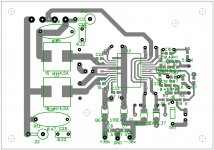
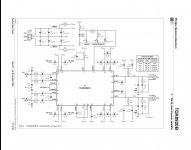
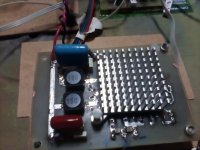
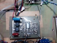
My TDA8920BTH is very hot, without load and input signal, about 80 C for 5 minutes. I made it on double-sides PCB, tracing almost like in datasheet (my PCB in attachment). Power supply is +/- 27 v, 4700 uf capacitor per rail. All of Components as described in datasheet, only inductors in output filter is slightly different. Chip is working, sound is very well, but chip is very hot. I thought that class D amplifier should not be HOT without load...may be my chip is broken?
my question: what is temperature of Your TDA8920BTH? and if someone had such a problem with this chip, how did you fix it?
Regards, Oleg
my question for people, who built (or use) amplifier, based on TDA8920BTH.
My TDA8920BTH is very hot, without load and input signal, about 80 C for 5 minutes. I made it on double-sides PCB, tracing almost like in datasheet (my PCB in attachment). Power supply is +/- 27 v, 4700 uf capacitor per rail. All of Components as described in datasheet, only inductors in output filter is slightly different. Chip is working, sound is very well, but chip is very hot. I thought that class D amplifier should not be HOT without load...may be my chip is broken?
my question: what is temperature of Your TDA8920BTH? and if someone had such a problem with this chip, how did you fix it?
Regards, Oleg
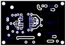
Attachments
You have included the snubber (10 Ohm + 2x220pF)?
Have you tried to disconnect the chokes on the side of the chip to see if the heating is from shoot-through currents or current going to the filter?
Do your filter chokes also become hot?
How much DC offset do you have at the outputs (with speakers connected)?
Have you tried to disconnect the chokes on the side of the chip to see if the heating is from shoot-through currents or current going to the filter?
Do your filter chokes also become hot?
How much DC offset do you have at the outputs (with speakers connected)?
FauxFrench, thanks for Your reply!
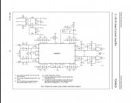
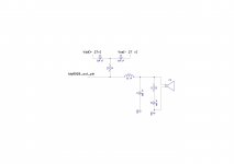
1. Snubber not include, because when I built my amp, I used datasheet of 2002 revision, this is one document which have a PCB image (that I copy). Snubber shown in datasheet of 2005. (In attachment You can see it).
2. I try to disconnect a inductors, but chip is hot
3. chokes is warm, slightly less of chip
4. DC offset is 40 mV.
without input signal i see a 314 kHz on the output
Attachments
Many thanks for the good information.
1. Snubber not include, because when I built my amp, I used datasheet of 2002 revision, this is one document which have a PCB image (that I copy). Snubber shown in datasheet of 2005. (In attachment You can see it).
I would see if I could fit snubbers at the rear side of the board. That will relieve the chip from some stress and improve EMI. In the 2002 version the 4.7Ohm/560pF is the snubber so perhaps it is already included.
2. I try to disconnect a inductors, but chip is hot
You use the "BTH" version for SMD mounting. How much heatsink do you use and is it well connected to the top of the chip? Even without loading by the output filter (and speakers) the chip still has power losses in particular from switching of the output power transistors. TDA8920 has a quiescent (idle) current of 50mA (typical) without the filters connected. With +/-27V supply that means some 3W power loss without any signal or filters connected. With the filters connected, it will be somewhat worse and you can expect some 4-5W power loss, still without a signal. TDA8920 is quite power hungry.
I have the "J" version which is easier to connect to a heatsink.
3. chokes is warm, slightly less of chip
If the chokes become more than 40 degrees Celsius, it could hint that they are not suited for 314KHz operation and may have too high core losses. What is the color of the choke cores? High core losses increase the chip losses because the chip has to supply the current that heats the cores at 314KHz.
4. DC offset is 40 mV.
Slightly high but not enough to cause important heating. So, OK.
without input signal i see a 314 kHz on the output.
That is correct. What you see is the residual of the carrier frequency. At the input of the filter you have a 54Vpp square wave signal (the carrier). At the output of the filter you have 2.72Vpp. The filter reduces the carrier frequency well but cannot remove it fully. All normal here.
NB: It is often stated that class D amplifiers have little power losses and the chips remain cold even without a heatsink. That is generally NOT true. A TPA3116 with a quiescent current half of what TDA8920 has and 19V supply generally remains cold. You have the double quiescent current and more than the double supply voltage so your losses are much higher.
Last edited:
FauxFrench, Thank you for the information!
1) i will try to add a snubber today
2) chokes is 15 uH, NPIS27H150MTRF(NIC components), DCR 0.027 Ohm, Idc=4.5A. This inductor what i now have. They are "for power design" inductor, but now I wait for Coilcraft inductor MSS1210-223MEB(smd) and RFS1113-273ME (thru-hole), which produce and recommended for TDA8920 by Coilcraft.
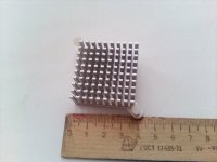
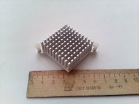
3) i use a heatsink from PC mother board, connect via mica plate and thermal grease. with heatsink, of course, chip not hot.
and, how is temperature of Your chip? and supply parameters?
regards, Oleg
1) i will try to add a snubber today
2) chokes is 15 uH, NPIS27H150MTRF(NIC components), DCR 0.027 Ohm, Idc=4.5A. This inductor what i now have. They are "for power design" inductor, but now I wait for Coilcraft inductor MSS1210-223MEB(smd) and RFS1113-273ME (thru-hole), which produce and recommended for TDA8920 by Coilcraft.
3) i use a heatsink from PC mother board, connect via mica plate and thermal grease. with heatsink, of course, chip not hot.
and, how is temperature of Your chip? and supply parameters?
regards, Oleg
Attachments
You probably have the snubbers already - 4.7Ohm/560pF.
So, with a heatsink you have no heating problems? You need a heatsink!
Chokes OK. I use similar. They should not operate much above 40 degrees Celsius.
I only have the TDA8920J chips, no time to use them yet. I have a TDA8954TH on a board and that one also becomes (very) hot without a heatsink.
Just a question, are you happy with your IkaScope? I did not know that brand but realized it is French.
ok, may be I need to make output stage as datasheet-2005(schematic in attacment)?
And I am saddened.. I make this Amp for replace my old amp based on TDA7294, for reduce temperature and connections in device. Now connections is more optimal, but temperature must be better...
one more question: if i connect output from chip via Schottky diodes to Vdd and Vss, Can it help to improve the performance of the chip?
About Ikascope. I got it for winning the contest from Elektor last year. it not bad, but if i have 300 euro, I'd rather buy a "second-hand" stationary device (in my country I can find oscilloscope from 100$...). look: Осциллограф HANTEK DSO5102P: 7 300 грн. - Оборудование Черкассы на Olx
it must better, and only 260$...
Attachments
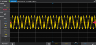
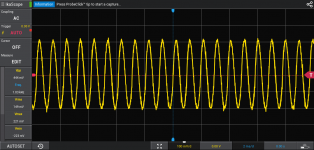
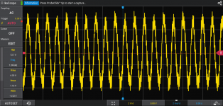
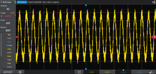
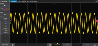
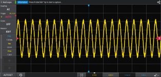
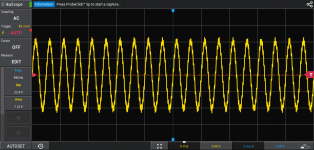
I feed on my amp of 1-kHz sinusoidal signal and measure a output, with and without load.
First, i get a sinus from microcontroller's DAC (pictures 1,2,3), second - from PC souncard (pictures 4,5,6).
Signal have some interference because it go thru sound processor (TDA7468)
Please, rate, is I get a normal output signal or not. And In your opinion, how does my amplifier work?
Regards, Oleg
Attachments
-
 1-sinus input from DAC.png96.9 KB · Views: 68
 -
 2-sinus out without load vol90%.png111.3 KB · Views: 68
 -
 3-sinus out with load vol90%.png110.8 KB · Views: 57
 -
 4-sinus input from soundcard.png94.3 KB · Views: 49
 -
 5-out sinus without load.png96.1 KB · Views: 32
 -
 6-out sinus with load.png91.7 KB · Views: 44
One small warning for a start: do not operate a class D amplifier without load. It may damage the output filter capacitor or the class D chip. The load resistance serves to damp the LC resonance in the output filter. No-load operation you can do with a class AB amplifier, NOT with a class D amplifier.
The Schottky diodes you propose are frequently implemented to protect the class D amplifier from surge-voltages generated by the output filter chokes. You won't hear a difference in the sound. I once "killed" a TDA8954 chip because I did not use such "catch"-diodes.
Yes, class D has been presented as hardly without power loss and many believe in this marketing slogan.
As you probably know, a class D amplifier typically operates with an efficiency around 90% at high output levels while a class AB amplifier around 70%. At low output levels their power loss is often comparable (in the order of 5W). In a class AB amplifier the quiescent current consumption is mainly used to bias the power stage while a class D chip is more complex and needs power to keep the carrier operating even without any sound. As normal music listening requires some 0.2-5W of power, most of us do not really use the efficiency gain of a class D amplifier.
The only way to have less idle power loss is to use a less powerful amplifier with little quiescent current. TPA3116/18 is known to be good in that respect.
From what I can see from your scope-shots, they look as expected: a 1KHz sine-wave with the residual of the 314KHz carrier on top. For a class AB amplifier we would be worried but a class D amplifier output will have a residual of the carrier frequency at the output as well. Even though your ears may be younger and better than mine, also you cannot hear the 314KHz.
Well done winning the Elektor competition! The IkaScope seems mainly intended for mobile service use where its compact size and low weight is an advantage.
Last edited:
- Status
- This old topic is closed. If you want to reopen this topic, contact a moderator using the "Report Post" button.
- Home
- Amplifiers
- Class D
- why TDA8920BTH overheating