News-Pre-launch of Lyngdorf MXA-8400 | Lyngdorf Audio
https://lyngdorf.com/wp-content/uploads/2019/02/MXA-8400-fact-sheet.pdf
Its a refinement of Ncore. No digital direct drive or a numerical amp.
https://lyngdorf.com/wp-content/uploads/2019/02/MXA-8400-fact-sheet.pdf
Its a refinement of Ncore. No digital direct drive or a numerical amp.
Just a quick note from my end to reduce the speculation
I must apologise I won't be able to join the discussion further after this post, because things are a bit busy here. Meaning that if anyone misunderstands what follows, I shan't be here to rectify matters")
The amplifier is not "DD". It's a straight self-oscillating fully analogue design, like all of my work of the past 15 or so years. All that time I've been saying that this is the best and most elegant way forward, and I daresay the new circuit confirms this. We've decided to call the technology Eigentakt, which is an obscure German term for self-clocking or self-oscillating. That would have been a giveaway, had Peter thought to mention the word.
I guess folks were assuming that digital was involved simply because the person to break the news is Peter Lyngdorf and he's of course historically been involved in open-loop "PWM power DACs", which is what I suppose you mean by DD. And of course, the technology historically used by Lyngdorf was developed by Lars Risbo who's my twin brother in this new venture, Purifi. He too feels no particular need to stick to digital control for its own sake. Being an engineer like me he's happy to use whatever seems the optimal solution at a given time.
So what's new in this amplifier? One thing is that I've developed a sampled domain model for self-oscillating loops that remains valid for all duty cycles, so it can predict closed loop response exactly under all conditions. This then allows finding a loop design that has very high loop gain (about 75dB at 20kHz, which is 20dB better than my previous designs) without running into stability problems near clip. A design procedure like this can't be patented because you can't prove that someone has been using it, so in a break from past style I'm not going to publish any details of this mathematical model. It's a trade secret, plain and simple.
Then there is the loop structure that allows better control of the closed loop frequency response. My previous amp* has approximately a 1st order roll-off. Now, since the output filter naturally has a second order roll-off it means that this amp could be overdriven with out of band noise from e.g. DSD recordings (in fairness, only when you cranked a quiet recording high). Also a first order response already droops noticeably by 20kHz which was sometimes remarked upon by numbers people. Eigentakt has a well-defined 2nd order response which stays dead flat in the audio band and rolls off in a fully controlled manner with a sensible -3dB point of 60kHz. The loop structure used to get this behaviour is subject of a patent application. A few other items are not really germane at the moment but were worthwhile enough to put in a separate patent application.
From a practical perspective, the enormous loop gain is partly used to allow more relaxed timing of the power stage without paying for that in distortion performance. As a result, the 400W power stage only has an idle loss of 1.7W or so. From dire experience I've learned that people don't perceive an amplifier as "cool running" if the idle losses aren't super low. It seemed a sensible move to get that sorted for once and all. In other words, the measurements you're seeing are those of a power stage actually optimized for idle loss (and hence, efficiency under real listening conditions).
Those asking "where are the patents", patience. It's a long procedure. First you file an application that gets bounced back and forth between the inventor and the patent office (with a patent lawyer in the middle), and 18 months after the first filing you see a published patent application. No sane inventor publishes details before that - those 18 months are actually there so you can take advantage of legal protection without having to tell your competitors your secrets. In other words: you will never find a patent for download when a new technology is announced. Of course, in sales communications one will easily say "patented" but actually it would be more correct to say "patent applied for" which should be enough of a heads-up for potential copycats.
Finally a note on how the various companies fit together. Purifi ApS was founded by Peter Lyngdorf, Lars Risbo and myself. No shares are owned by any of the other companies we're involved in. Purifi is run independently and will eventually supply technology to a broader base of customers. But it should be obvious why our lead customers would come from our own orbit...
_______________________________
*Forming a new company of course involved quitting my previous position, which I'm now competing with. I think it's only polite not to bandy around any of their trade names, in particular since in private we're still friendly.
I must apologise I won't be able to join the discussion further after this post, because things are a bit busy here. Meaning that if anyone misunderstands what follows, I shan't be here to rectify matters
Blah snipped.
Given you have immediately exited the conversation I will not explain just how well I do understand the part that has been snipped and its implications. There is a chance we may have to "rectify matters" at a later date.
Last edited:
Hello All,
My post is not meant to speculate on the upcoming patent by Mr. Putzeys et al. I'd like to comment on Mr. Putzeys US Patent [7,113,038]. It is entitled "Power Amplifier" and was dated Sep. 26, 2006. Please note:
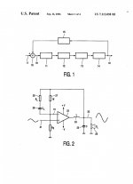
1. The left view picture is page 2 of this patent. Focus on Fig.2. I do not know whether Fig.2 pertains to the commercial Ncore amplifier; but it is suitable for this following discussion.
2. Fig. 2 struck me as an Analog Power Amp with an intentional self oscillating ability to make it Class D. Can I [in theory] improve it? Maybe as follows!
3. The right view picture is the basic schematic of Fig.2 plus the inclusion of Positive Current Feedback [PCF] therein. This is the hypothesis which is meant to improve the performance of the resulting amp.
4. Rsense [~0.3 Ohm] is connected in series with the loudspeaker load [Zl]. It senses load current as the resultant Vsense; which is the [PCF] signal. The phase of the input signal to the comparator, the power output signal and that of Vsense are in alignment [in phase].
5. Vense is sent to the non-inverting input of the comparator via Rin [given as 47 K].
6. PCF increases the intrinsic open loop gain of the parent amp. Its value is it gives the new amp more gain to sacrifice at a constant overall negative feedback due to Rf and Rg. Thus, the resultant amp is expected to have a lower output impedance [higher damping], and a lower distortion than the parent. Output noise may rise!
7. A side effect of PCF in this [theoretical] amp is its propensity to oscillate beyond a certain level of Vsense. Self oscillation may be a plus; after all this is an important function of Rl and Cl in Fig. 2 of the parent amp. Can one do without Rl and Cl; but add a generous level of Vsense so as to enable a simultaneous self oscillation?
I hope the above is a possible food for thought and entertainment.
Best
Anton
My post is not meant to speculate on the upcoming patent by Mr. Putzeys et al. I'd like to comment on Mr. Putzeys US Patent [7,113,038]. It is entitled "Power Amplifier" and was dated Sep. 26, 2006. Please note:
1. The left view picture is page 2 of this patent. Focus on Fig.2. I do not know whether Fig.2 pertains to the commercial Ncore amplifier; but it is suitable for this following discussion.
2. Fig. 2 struck me as an Analog Power Amp with an intentional self oscillating ability to make it Class D. Can I [in theory] improve it? Maybe as follows!
3. The right view picture is the basic schematic of Fig.2 plus the inclusion of Positive Current Feedback [PCF] therein. This is the hypothesis which is meant to improve the performance of the resulting amp.
4. Rsense [~0.3 Ohm] is connected in series with the loudspeaker load [Zl]. It senses load current as the resultant Vsense; which is the [PCF] signal. The phase of the input signal to the comparator, the power output signal and that of Vsense are in alignment [in phase].
5. Vense is sent to the non-inverting input of the comparator via Rin [given as 47 K].
6. PCF increases the intrinsic open loop gain of the parent amp. Its value is it gives the new amp more gain to sacrifice at a constant overall negative feedback due to Rf and Rg. Thus, the resultant amp is expected to have a lower output impedance [higher damping], and a lower distortion than the parent. Output noise may rise!
7. A side effect of PCF in this [theoretical] amp is its propensity to oscillate beyond a certain level of Vsense. Self oscillation may be a plus; after all this is an important function of Rl and Cl in Fig. 2 of the parent amp. Can one do without Rl and Cl; but add a generous level of Vsense so as to enable a simultaneous self oscillation?
I hope the above is a possible food for thought and entertainment.
Best
Anton
Attachments
6. PCF increases the intrinsic open loop gain of the parent amp. Its value is it gives the new amp more gain to sacrifice at a constant overall negative feedback due to Rf and Rg. Thus, the resultant amp is expected to have a lower output impedance [higher damping], and a lower distortion than the parent. Output noise may rise!
ANY pos feedback increases the open loop gain. What is the reason that you specifically want to use current feedback?
Jan
It would be interesting to know whether the output devices are GaN, and the switching frequency, but I suppose that this information is still kept under lid.
Buy one and see what type the transistors are, and measure the frequency.
Then tell us ;-)
Jan
ANY pos feedback increases the open loop gain. What is the reason that you specifically want to use current feedback?
Jan
Thanks for your post. I fully agree with your statement regarding using positive voltage feedback [PVF]. No specific reason to choose PCF over PVF. I've played with both feedback types in analog power amps. Both are worthy of experimentation in Class D to possibly determine an edge for one type or the other.
Best
Anton
It would be interesting to know whether the output devices are GaN, and the switching frequency, but I suppose that this information is still kept under lid.
They are MOSFETS. The Philips UcD power amp is the one which pertains to Fig. 2 in my earlier post #25. Please see "Favorite Threads and Posts in "Class D" Forum. Post #3 therein by DIYer BWRX shows the link " Philips UcD Application Note". Its thread describes the amp's schematic and other valuable details. Mr. Putzeys is the inventor and Philips is the Assignee [owner] of US 7,113,038 patent. Page 6 of this patent shows the amp's switching frequency of 415 KHz.
Mr. Putzeys is the inventor of the newer US 8,049,557 and US 8,289,097 patents. Their Assignee is Hypex Electronics B.V. Their commercial amps may have been called "Fusion" and "NCore".
Best
Anton
All this and and years later the NCore 400 schematic leak is public domain knowledge look for NAD M22 Service Manual.
Now there is a claim that a newer modulator patent has been filed, for a DiYer these are negligible aspecs. higher modulator gain? lower distortion? lower idle loss?
Now there is a claim that a newer modulator patent has been filed, for a DiYer these are negligible aspecs. higher modulator gain? lower distortion? lower idle loss?
All this and and years later the NCore 400 schematic leak is public domain knowledge look for NAD M22 Service Manual.
Now there is a claim that a newer modulator patent has been filed, for a DiYer these are negligible aspecs. higher modulator gain? lower distortion? lower idle loss?
Thanks Reactance. NAD M22 has an impressive performance. A harmonic distortion of <0.005% from 250 mW to rated power, and an 800 damping factor; to name a few. Its service manual is posted in HiFi Engine.
I bought via eBay UCD180LP made by Hypex Electronics. Its construction is a masterpiece of creativity and genius. LP stands for low profile. The back side of this amp's pcb is a neat field of SMDs. The two mounting holes of its small heat sink appear to fit those of a TO-3; for ready mounting to a larger one. This amp is art too!
My objective is to imbibe this amp with positive feedback [PF]. I expect [PF] to refine the subjective performance of this amp and its loudspeaker load in the listening room.
I have been prepping the stage to DIY UCD180LP by experimenting with analog and a Class T power amps. The outcome is positive. I hope to share/post such info in this thread; granted the Moderator deems it fit; as I am off-topic/title.
Best
Anton
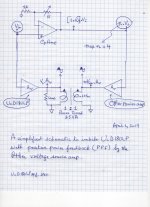
Infusing UcD180LP with positive feedback
The attached schematic is a simplified circuit of a prototype which I am using to infuse UcD180LP with positive feedback. This approach is most likely adaptable to other Class D amps. I have been listening to it. Details and pics to follow! Please note:
1. The 1:1 toroid power transformer. It transfers positive power feedback [ppf] from the Other voltage source power amp on the right to UcD180LP.
2. The phase of the toroid's windings and the phase of the power output signals from both amps flanking the toroid. All are and must be in-phase.
3. UcD180LP drives the Load.
4. Set-up must be as follows so as protect the equipment and to generate a subjective baseline performance.
a). Remove the toroid from the circuit so as to separate the operation of the power amps.
b). Load each amp with an 8 Ohm non-inductive power resistor.
c). Adjust the value of R in the Op Amp circuit so as to establish power output signals which are initially equal in amplitude [baseline]. Must note the resultant voltage gain of the Op Amp; because it is the baseline value of [n].
d). Confirm that the power output signals across the 8 Ohm load resistors are in-phase. A must!
e). Put back the toroid in the circuit and load UcD180LP only with an 8 Ohm power resistor. Power up both amps, and confirm that the power output signals across the windings of the toroid are equal in amplitude and are in phase.
f). Minimize the amplitude of the [equal] power output signals. Connect your loudspeaker load to UcD180LP. This system is stable against oscillation.
5. I put the loudspeaker in a corner of the room and listen to the system's output music at the diagonal corner. I'll explain later.
6. The value of R in the Op Amp circuit is slowly increased so as to increase its voltage gain and thus increase the value of the new [n] by no more than 4. The system is in [ppf] mode! It will oscillate. UcD180LP blew its two [0.2 A] rail fuses when I infused it with a [ppf] from a value of n=5. There's a limit to infusing it with [ppf]; no fooling.
7. The Other voltage source power amp dumps a preset level of power in UcD180LP across the toroid. It is [ppf]. It has valuable consequences on the subjective performance of the system in the listening space.
To be continued..
Best
Anton
Attachments
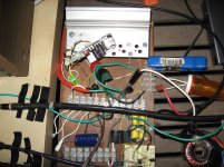
Details on pics.
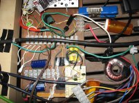
1. UcD180LP is bolted [with heat transfer goop] to the silver heat sink. Its inherent small heat sink [internally at common potential] is mounted on the two normal TO-3 mounting holes. Very appropriate, and a bright move by Hypex.
2. Color coded wires were soldered to its block connector. They terminate at the white top European-style barrier strip. UcD's power rail connections [+/-45 VDc] are shown at the left side of this strip. They are fused with two X-Mas light bulbs; [~0.2 A each].
3. The black box at the top right view is a Class T power amp from Stellar Labs [got it from MCM Electronics a while ago]. Its power output is BTL and infuses positive power feedback [ppf] into UcD180LP. It has an input volume control which is used to [carefully] adjust the extent [ meaning the value of n] of [ppf] to UcD.
4. The 25 VA toroid is VPT48-520 from TRIAD Magnetics. It has two 115 VAc primaries and two 24 VAc secondaries. One primary is parallel connected [in-phase] to one secondary, and the other primary is connected to the second secondary. The resultant is the 1:1 power transformer used in the prototype.
5. The proto-board at the bottom right of the pic is the Op Amp-based differential input circuit to UcD as proposed by Hypex. Except; each side has a gain of 1. The Op Amp's diff outputs are coupled to UcD's inputs c/o the yellow PE capacitors [5uF each].
6. The bottom European style strip connector has the voltage regulator [+/-8 Vdc] to the Op Amp and its input signal connections.
7. The loudspeaker cable is green. The black-colored cables are Monster types [vintage 1980's].
8. The "Other" amps which I've also used to imbibe UcD with [ppf] was a channel of a Threshold S/150 power amp, and the amp of a Kenwood receiver [KR-6050]. The net compound power amp which was assembled form each of the three [ppf] infusers was stable against oscillation; granted that I was not overly generous with [ppf].
Pending is my reason to put its loudspeaker in the corner! This system sounds great regardless of the location of the loudspeaker. Evident differences in subjective performance do emanate as a function of the infuser amp and the loudspeaker location.
Best
Anton
Attachments
Subjective Refinement
Why put and listen to a loudspeaker in corner? Here's my reasoning:
1. Suppose a power amp using only overall negative feedback [ONF] like UcD180LP or other drives a loudspeaker which sits in the corner of the listening room.
2. My hand gently pushes in the woofer cone. The amp uses its [ONF] to push back against my hand so as to restore the original position of the woofer's cone. My push-in-action generated an equal and opposite push-out-reaction by the amp.
3. Corners are rich in transient standing waves[TSW] during listening of bass-rich music. By analogy to point [2] above, the power amp pushes against a [TSW] when it pushes in the cone of the woofer. The consequence of this action may be neutral in degrading the sound pressure of [TSW], or worse by intensifying its amplitude which is acoustically bad.
4. Suppose the power amp has/uses only positive overall feedback [POF]. My hand pushes gently on the loudspeaker's cone. The response of the power amp is to suck-in the woofer's cone. It'll do the same for a [TSW].
5. Here's the important connection worthy of your attention. As the high pressure [TSW] pushes against the cone, the amp draws-in the cone which continues to move inward. The amp creates a resultant vacuum at the cone's interface. This vacuum lowers the sound pressure of the offending [TSW]. It minimizes or kills the amplitude of [TSW] which is the objective or the subjective refinement. It clarifies the bass.
6. UcD180LP has an inherent [ONF]. I infused it with [POF] as I taught earlier. It drives the loudspeaker [ADS L-730] which sits in a corner of the listening room.
6a. In the absence of [POF] in UcD180LP, bass in music sounds poor [mud]. This happens regardless of any other amp used; be it a Threshold S/150, a Kenwood, or a Class T...etc.
6b. Imbibing UcD180LP with [POF] cleans up the bass region in the corner. Tight and detailed bass dominates which is the subjective refinement.
7. Music sounds great with the loudspeaker driven by UcD180LP {ONF+POF} when put in the room but not in any corner.
8. The inclusion of [POF] in new [and old] generation power amps is beneficial to the sound of music, and is thus highly recommended.
Best
Anton
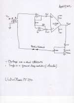
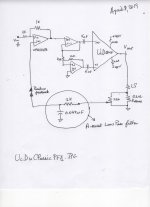
The attached schematics show the "classic or text-book " approaches to infuse UcD180LP with positive feedback. Both prototypes work. A sense resistor [0.2 Ohms] in series with the loudspeaker load develops a voltage drop across it as a function of the load current which varies with the frequency of the music. This resultant voltage is returned to the front end of UcD. One signal phase increases gain [that's PF] and the opposite phase decreases gain of UcD180LP; that is negative feedback [NF].
Both prototypes have common behaviors when using a 100 Hz test signal [to test the limits of PF], and ADS L730 loudspeaker load:
1. A maximum 12 dB gain [Vout with PF =4 x Vout without PF] is achieved [carefully] before the rail fuses blow.
2. The [subjective] sound of ADS L730 changed as [PF] is varied as a function of its extent. This change is not subtle whether the loudspeaker sat in the corner or inside the room. Treble is strongly magnified or heightened with a threefold [PF] gain. [PF] upset the natural balance of this loudspeaker as designed by ADS [Analog and Digital Systems]. It is fair and accurate to say its audio engineers used test power amps utilizing only overall [NF] so as to give it its characteristic sound. It also follows that different loudspeakers will react differently due to [PF].
3. I did not know how to limit the bandwidth of the [PF] signal in the left schematic which used a ground fault isolator. This circuit is easy!
4. The right schematic shows the encircled low pass filter which limits the bandwidth of the returning signal to the front end. Treble increases further as the value of the capacitor [0.047 uF] in the low pass filter is decreased.
5. I connected two 15-inch [unenclosed] full-range [FR] [loudspeakers in parallel; net 4 Ohms. They are bolted to the ceiling of the listening room and are angled to aim at either side of my head as I lay on the room floor. Even without a crossover, the rail fuses blew at a [PF] extent of 12 dB with a low pass filter.
6. I listened to the [FR] loudspeakers using only a 2.3 dB extent of PF [Vout with PF = 1.3 x Vout without PF] as suggested by Mr. Nelson Pass for his F7 power amp which uses [ONF] and [PF]. The right prototype/schematic was used. The subjective sound due to this lean extent of [PF] is fully agreeable. I noted a perceptible difference due to this [PF].
7. The subjective sound of ADS due to this classic approach [aka intra PF] was totally different from that shown in the previous posts which used a separate amp for the infusion [inter PF].
Best
Anton
Attachments
Last edited:
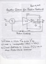
Please find attached a simplified power amp schematic based on UcD180LP which uses another and facile signal source for positive feedback [Vpf].
I like it because [1]. It is simple to implement. [2]. Most importantly, [Vpf] was found to be predominantly focused and/or mostly localized in the operation of a loudspeaker's woofer. [3]. The amp is stable against destructive oscillation and the system sounds great; open and refined.
Please note the following in the schematic. UcD has a dual function:
1. It is a voltage source amp [VSA] which drives the loudspeaker load as it is designed to do so.
2. It a a simultaneous current source amp [CSA] which drives the sense [0.2 Ohm] power resistor load. The junction of the two batteries [its dual voltage PSU] is normally ground or common. In this case, [Vpf] is the resultant voltage source which is derived from mostly the current which flows in the sense resistor from the power output stage of UcD.
3. I have redefined the location of common or ground. Didn't seem to disturb the amp's operation!
4. [Vpf] is a clean signal which is free of UcD's inherent oscillation signals.
5. [Vpf] is summed with the input music signal by an Op inverting Amp and then presented to UcD's input. A detailed schematic will follow.
6. I am using a linear dual voltage PSU [Variac adjustable up to +/- 50 Vdc] in a dead Radio Shack receiver.
Can one use The HYPEX SMPS1200A180 [+/-46 Vdc] which is recommended for UcD180LP in this specific application? I do not know the answer.
Best
Anton
Attachments
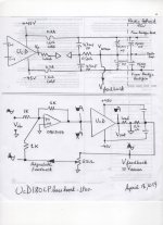
The attached schematic is in two parts.
{A}. The upper part details the +/-45Vdc linear PSU which I am using to power UcD180LP. Please note:
1. The power cord of the Radio Shack [RS] receiver is driven by a Variac. Its power switch is first turned on, and this PSU's voltage is raised slowly to the target value. I usually settle it at +/-25 V to start. On turn-off, the power switch of [RS] is turned off. It discharges the electrolytic capacitors through power resistors in it. I always return the Variac knob back to zero Volts AC. The orange cord in the pics of post#36 is a 3-conductor; incoming from [RS] to UcD.
2. The capacity of the electrolytic capacitors in this PSU seems generous. These caps are old [1980 vintage] and most probably their actual capacity is exaggerated.
3. The 0.2A fuses are X-mas light bulbs. I've blown many pairs in experiments.
4. The feedback signal or [Vsense] emanates from the center tap of the [RS] power transformer.
{B.} The bottom part of the view is the resultant prototype. Please note:
1. The phase-splitter which drives UcD is not shown so as to simply.
2. This schematic is all about the phase of the signals. They are drawn half-shaded to emphasize their phase relationships in the circuit. The phase of the signals at Vin to the OpAmp, at Vout of the Op Amp, and at Vout of UcD are accurately shown. They are the reference signals against which the phase of [Vsense] is compared.
3. [Vsense] is depicted to be in-phase with [Vin] to the OpAmp. It is drawn with a small [V] on top of the shaded part and is also idealized to be exactly 180 degrees out of phase with UcD's [Vout]. The phase of [Vsense] is expected to lag the phase of [Vout]; because the current which flows through the reactive woofer [and simultaneously through 0.2 Ohms] lags UcD's voltage [Vout] driving it.
4. The input signal [Vin] to the OpAmp and [Vsense] are summed or added. They are separated as depicted at the output of the OpAmp. This is positive feedback and a consequent loudness boost by the woofer.
5. The loudness boost is adjustable c/o the 25 Ohm resistor which is wired across the sense resistor [0.2 Ohms]. I do not understand why this boost is only focused in the woofer.
I'll show in the upcoming post the schematic for increasing negative feedback in the system.
Best
Anton
Attachments
- Status
- This old topic is closed. If you want to reopen this topic, contact a moderator using the "Report Post" button.
- Home
- Amplifiers
- Class D
- Ncore design refinement