I have three TDA8954TH boards and today they all play very well. One is the board you have but I modified it to stereo.
Two of my TDA8954TH boards performed poorly for a start because the snubber implementations were seriously wrong. I changed the snubber circuits to the values in the datasheet and after that they worked much better.
It is not that the TDA8954TH IC is poor or useless, there are unfortunately people who produce poor TDA8954TH boards. The TDA8954TH BTL board you have and I modified, is not designed for 420W as the sellers promise.
Last edited:
It is not that an amplifier has a specific operating voltage and outside of that operating voltage it does not work. An amplifier has a supply voltage operating range. If it is a single-chip amplifier with the power switches integrated, it is easy to see the operating range in the datasheet. For the IRS2092, it is a bit more tricky as it has not got power switches integrated and has more chip supply voltages. Thus, the supply voltage range is dependent on the actual design. Therefore, you have to look in the specifications for the actual amplifier design.
I have very little experience with the IRS2092 chip. A have one IRS2092 board (mono) for up to 200W or 250W as I recall. I tested it with a +/-24V supply voltage, as I recall, and it worked. I never found time to investigate its qualities further but I know that there are member at this forum with elaborate experience with IRS2092. IRS2092 and TDA895x operate from a symmetrical supply voltage (SE coupling), not a lot of other class D chips do.
Yes but can't find any infos in the data sheet about voltage for this chip.
And like you said, dependent of the design of the board for modules that are sold on the web today.
You are right, it is not all boards that show the lower power supply voltage.
Some that do:
IRS2092S Class D Mono Digital Amplifier Board module 200W High Power HIFI Stereo Amp Sound Player Board 20Hz 20KHz diy kit|Operational Amplifier Chips| - AliExpress
New IRS2092 Class D 200W Mono Audio Power Amplifier AMP Assembled Board|Operational Amplifier Chips| - AliExpress
Lusya L15DSMD IRS2092S High power 250W Class D Audio Digital Mono Amplifier Board F4 003|Amplifier| - AliExpress
L15DSMD IRS2092S 250W Class D Digital Mono Amplifier Board Module High Power Assembled|Integrated Circuits| - AliExpress
Lusya IRAUD200 High Power Digital audio Amplifier Board IRS2092S Mono 500W HI FI Amplifier finished Board G9 009|Amplifier| - AliExpress
https://www.aliexpress.com/item/100...earchweb0_0,searchweb201602_,searchweb201603_
You can use your SMPS as a 76Vdc supply, BUT only with an 8 Ohm load. 76Vdc supply for a class D amplifier leaves you with more than 300W output power in 8 Ohm (BTL coupled amplifier board). In 4 Ohm that would be 700W but that the SMPS cannot deliver.
As long at none of the two SMPS have a connection to protective earth, it should in theory be possible. How much noise it will introduce I cannot tell. The amplifier must be SE-coupled (one speaker terminal to ground) but in theory 700W in 4 Ohm should be possible because you use two SMPS. +/-76Vdc means 150Vdc from + to - and that is very dangerous for you in particular. The more power you design for, the more power you have to cause damage on the electronics in case something goes wrong.
As long at none of the two SMPS have a connection to protective earth, it should in theory be possible. How much noise it will introduce I cannot tell. The amplifier must be SE-coupled (one speaker terminal to ground) but in theory 700W in 4 Ohm should be possible because you use two SMPS. +/-76Vdc means 150Vdc from + to - and that is very dangerous for you in particular. The more power you design for, the more power you have to cause damage on the electronics in case something goes wrong.
Last edited:
Output power depends on supply voltage (and speaker impedance). As it is 76Vdc, the supply voltage is fixed and you will need to increase the speaker impedance above 8 Ohm to have less output power.
Finding a class D amplifier board that can operate (safely) at 76Vdc may not be so easy.
Finding a class D amplifier board that can operate (safely) at 76Vdc may not be so easy.
@FauxFrench sir, I followed your instructions but I don’t need stereo mod, just need it stop hum and noise to apply as a mono subwoofer amp.
I already done:
* replaced the initial snubber components with correct values (10 Ohm/220pF/220pF) > DONE
* used a slow-running, low-noise fan for the heatsink > DONE
* replaced the six “ChongX” 2200uF/50V power rails capacitors with Nichicon types > CHONGX CAPS still there but I add 2x20.000uf nichicon caps connect to power rails
* replaced the initial 1 Ohm noise reduction resistors with 10 Ohm ones > Board has 100 smd resistor in the begining
* added two 1uF ceramic capacitors in parallel with C20 and C21 for better noise decoupling > DONE
* added two 47K resistors between each input terminal and ground > I connect 22k resistor between + and – inputs, idk if it has any effect?
* inserted an insulating sheet between the TDA7854TH housing and the heatsink, adding a fine layer of cooling paste on both sides > DONE
Compare with origin board, the hum noise decreases like a half after doing changes above. When no input or I short circuit + and – input, it is dead silent. But when connect input, play music and pause, the hum still loud enough to hear even I stand 1 metre nearby
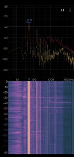
This picture I mesuare hum noise with my phone 0.3m near my subwoofer driver before changes. now it decreased, hum noise remain about -50-55db but still hearable
I sure think this loud hum is the reason I get this board for very cheap price. Is there anything I can continue do to remove this hum sir?
I already done:
* replaced the initial snubber components with correct values (10 Ohm/220pF/220pF) > DONE
* used a slow-running, low-noise fan for the heatsink > DONE
* replaced the six “ChongX” 2200uF/50V power rails capacitors with Nichicon types > CHONGX CAPS still there but I add 2x20.000uf nichicon caps connect to power rails
* replaced the initial 1 Ohm noise reduction resistors with 10 Ohm ones > Board has 100 smd resistor in the begining
* added two 1uF ceramic capacitors in parallel with C20 and C21 for better noise decoupling > DONE
* added two 47K resistors between each input terminal and ground > I connect 22k resistor between + and – inputs, idk if it has any effect?
* inserted an insulating sheet between the TDA7854TH housing and the heatsink, adding a fine layer of cooling paste on both sides > DONE
Compare with origin board, the hum noise decreases like a half after doing changes above. When no input or I short circuit + and – input, it is dead silent. But when connect input, play music and pause, the hum still loud enough to hear even I stand 1 metre nearby
This picture I mesuare hum noise with my phone 0.3m near my subwoofer driver before changes. now it decreased, hum noise remain about -50-55db but still hearable
I sure think this loud hum is the reason I get this board for very cheap price. Is there anything I can continue do to remove this hum sir?
sorry, missing img
An externally hosted image should be here but it was not working when we last tested it.
Attachments
@ponyta,
You have done well and tell us important information.
When the amplifier is not connected to a source or the input is short-circuited, there is no noise. Thus, it seems not to be the amplifier power supply in itself that causes the problem.
When you use a source but stop the music playing, you clearly hear hum. Thus, the hum origins from the connection with the source OR, if you use a smartphone as source, the smartphone disables the headphone output when you stop the music in order to save battery.
First test for you to do is to connect your smartphone as source, without being connected to a charger, and play music from the smartphone while you slowly reduce the volume on the smartphone to zero (don't press stop or pause). This way the headphone output is not disabled. Do you still hear hum-noise?
Last edited:
Thank you FauxFrench!
I did connect my board with a smartphone, play music, adjust volume to 0, and there no hum.
But whenever my hand touches the phone or the wire. I heard the hum, it is loud and sensitive even I come nearby the wire, not touch it.
Back with my subwoofer filter preamp circuit, I try with a different amplifier board (mono class a/b run 1pair a1943-c5200 transistors), it doesn't hum at all
(my preamp board quite similar here: NE5532 Bộ Lọc Thong Thấp Ban Loa Sieu Trầm Am Lượng Ban Module Khuếch Đại 9 15V Lọc Mo đun|Integrated Circuits| - AliExpress)
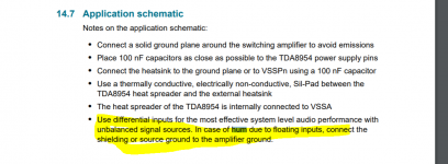
Reading tda8954 datasheet have some info, so I think maybe mass connect both 2 boards could fix that 50hz background hum.
(GDN mass connect, ground shield... etc I don't know what exactly it is or how to do. I'm so amateur, really need help).
ah, I am sorry for replying late, so busy with the living thing.
I did connect my board with a smartphone, play music, adjust volume to 0, and there no hum.
But whenever my hand touches the phone or the wire. I heard the hum, it is loud and sensitive even I come nearby the wire, not touch it.
Back with my subwoofer filter preamp circuit, I try with a different amplifier board (mono class a/b run 1pair a1943-c5200 transistors), it doesn't hum at all
(my preamp board quite similar here: NE5532 Bộ Lọc Thong Thấp Ban Loa Sieu Trầm Am Lượng Ban Module Khuếch Đại 9 15V Lọc Mo đun|Integrated Circuits| - AliExpress)
Reading tda8954 datasheet have some info, so I think maybe mass connect both 2 boards could fix that 50hz background hum.
(GDN mass connect, ground shield... etc I don't know what exactly it is or how to do. I'm so amateur, really need help).
ah, I am sorry for replying late, so busy with the living thing.
Attachments
No, I just connected the boards together, all on the wooden tabletop:
A-preamp board
B-TDA8594 btl board
C-Mono A/B amp board
B, C run a 24-0-24V power supply and no hum when no input, A run a different dual 15Vs
A+C--> no hum
A+B--> hum
I just thought about floating input in tda 8954 datasheet
A and C have 0v as (-) sound in signal so just connect signal wire and they are grounded together
but B is BTL, I don't know whether sound signal (-) (0v in A) can be wired to 0v in B to fix hum??
Sorry, this time I am late.
There are two types of constructions:
a) Those with two symmetrical supply lines (+ and -) with a further ground connection (called GND or 0V).
b) Those with only a single supply line (+ only) with a further ground connection (called GND or 0V).
The grounds are always connected together, never GND from a single supply construction to minus (-) of a dual supply construction.
Thank FF, it seems there is no way to fix my board. I removed the rectifier bridge, use outside power but still nothing change about noisy hum.
Seeing some part of my board is not very similar to yours. I doubt it uses the wrong value of other capacitors. Also i quite want to fix it because this board gives a good bass quality (except it's noisy) i don't see in other board that cheap
Seeing some part of my board is not very similar to yours. I doubt it uses the wrong value of other capacitors. Also i quite want to fix it because this board gives a good bass quality (except it's noisy) i don't see in other board that cheap
Hi @FauxFrench , Im looking for a amp to replace my aging tda8920( which loudly thuds at a rapid pace then gradually slows down to disappear at power on) board with a dual tda8954 chip board to drive my two subs (4ohms), power supply will be 24v, have two torroids available of the same model.
TDA8954TH Class D High Power Dual-Channel Digital Audio Amplifier Board 420W*2 700828400180 | eBay Is the one I'm looking at, my question is will it be an issue to use 4 ohm subs with the chips being in BTL mode and recommend to be used with 8 ohms. Not looking for high power, 200 a channel would do, more like 100 continues maybe with extra headroom to handle peaks at low freq around 20 30 Hz them being sealed subs.
Alternate option I have is the same single chip model you had an issue with highs being Sharp and distorting which required a snubber circuit correction.
Your help will be greatly appreciated.
You can use a different speaker impedance than recommended if you eventually adapt the supply voltage. I will explain the considerations in detail for less experienced members. You can always use a higher speaker impedance than recommended without changing the supply voltage. The result is less maximum output power and for class D amplifiers a change of the frequency response in the high treble (due to a change of the output filter damping). The more tricky situation is when a lower speaker impedance than recommended is used and the load current increase.
We normally define the maximum output power as the output signal level where voltage clipping starts occurring. Thus, where the supply voltage limits the output voltage from going any higher (or lower). Voltage clipping typically starts occurring at a THD level in the order of 1%. Because amplifiers normally also include a current limitation for protection of the amplifier circuit, we could also talk about current clipping. The problem with current clipping is that it often arrives much more abrupt than voltage clipping and causes a much higher distortion. While voltage clipping causes a gradual increase in distortion when the clipping level is exceeded, current limit protection is included to protect the amplifier circuit without disregard to the distortion we notice. Some chip-amps can do an almost flat current limitation reminding of voltage clipping, but in particular class D amplifiers do dramatic things to limit the current. Therefore, the golden rule in amplifier design is that at no point is the current in the load, the speaker, allowed to exceed the current limit. For the TDA8954TH chip the current limit value is 12A (minimum and peak).
But as we consider the speaker impedance to be mainly resistive, we always have the possibility to reduce the maximum load current by reducing the supply voltage.
In the past the speaker was connected in “SE-coupling”, between the amplifier circuit output terminal and the ground wire (‘0”) for a symmetrical supply voltage. The maximum voltage across the speaker terminals was the voltage from one supply rail to ground. For the TDA8954TH chip that voltage is as an absolute maximum 42.5Vdc.
But, clever people realized that two amplifiers operating in counter-phase could be used for a single speaker such that the full rail-to-rail voltage could be put on the speaker terminals such that both the voltage and resulting current would be the double, and the power thus four times as much. This is the “BTL-coupling”. The problem with the BTL coupling is that you tend to loose track of the maximum load current and risk current limitation in the amplifier if not prudent.
For the TDA8954TH chip with an absolute maximum supply voltage of +/-42.5Vdc. the peak BTL voltage across the speaker is 85V. 85V over 8 Ohm leaves a current of 10.6A peak (below the current limit of 12A) but in 4 Ohm it becomes 21A peak, which is far above the current limit. Therefore, only 8 Ohm is recommended for BTL operation at full supply voltage.
But, we could reduce the supply voltage to +/-20Vdc in which case the peak current is 10A in 4 Ohm - well below the current limit. Or if we already have a+/-40Vdc power supply and a 4 Ohm speaker, we could change the coupling from BTL to SE in which case the peak current remains at 10A.
In both cases the maximum output power in 4 Ohm is the same, at 200W.
In the particular case with two 24Vac transformers, the BTL→SE change could be the way to go. If redundant TDA8954TH channels are then not used, the inputs to those channels should be short-circuited to signal ground and the output filter disconnected from the channel outputs.
Apart from load current limits there are other issues to worry about such as the thermal design and PCB layout for high currents. The amplifier board you link to I find aesthetic but I would worry about the result if it was left to operate at 2x420W (in 8 Ohm) for just a short period. Theoretical and practical performance can deviate a lot.
- Home
- Amplifiers
- Class D
- TDA8954th btL amplifier