Hi
I am happy that you are the first to write some comments about sound")
i had exactly the same impression.. i compare to the "same" range of amp = fx502spro mod.
the sound is impressive dark, dark and deep bass good musicality...
...but is pushing hard a lot of voices and instruments, yes violin and piano is too hard...the out swing is too abrupt.
for playing music you have to care about not shorting the speaker outlets an pulling away the pcb...-this amp is very tiny
thanks for your hint...
I am happy that you are the first to write some comments about sound
i had exactly the same impression.. i compare to the "same" range of amp = fx502spro mod.
the sound is impressive dark, dark and deep bass good musicality...
...but is pushing hard a lot of voices and instruments, yes violin and piano is too hard...the out swing is too abrupt.
for playing music you have to care about not shorting the speaker outlets an pulling away the pcb...
-this amp is very tinythanks for your hint...
I've been listening a while and figure the next 'bottleneck' is most likely the switching reg powering the VDDA rail. Its a LM5010 set to 5V, I figure if I set it to say 7V with a resistor tweak I can put a linear reg between it and the TPA3220. Let's see what happens....
aaahh... an expert is quicker in measure and doing as i am in reading
typo in the datasheet
3.5.2.2 PVDD Only (12 V to 30 V) LDO Mode
This power mode is the default setup when the board is tested and shipped. The user can connect any
valid supply voltage to J1 and the onboard LDOs will generate the required non-PVDD voltages. PVDD
itself always connects directly to the TPA3220 PVDD pins. Setup for this mode is the same as described
in Quick Start (BTL MODE) .
J1 is the input 3.5mm analoge input Jack
J6 connector is the Terminal for Power supply
Hi
nooby question
As i see in all datasheets (blockdiagram, e.g.TPA3251 Figure 22) that an internal DC blocking caps are existing. ....correct?
additionally at the schematic and on the real EVM board there are extra DC blocking caps with 10µF.
Why ? is the internal DC cap to "weak"?
looking at the TPA3220 micro EVM datahseet
Why is at the TPA3220 the input DC coupling cap "just" 1µF? if you follow the 3,5mm jack....and the signal goes directly into the chip
chris
Hi
nooby question
As i see in all datasheets (blockdiagram, e.g.TPA3251 Figure 22) that an internal DC blocking caps are existing. ....correct?
additionally at the schematic and on the real EVM board there are extra DC blocking caps with 10µF.
Why ? is the internal DC cap to "weak"?
looking at the TPA3220 micro EVM datahseet
Why is at the TPA3220 the input DC coupling cap "just" 1µF? if you follow the 3,5mm jack....and the signal goes directly into the chip
chris
Hi Chris,
In the TPA3251 datasheet, figure 22, I see “Input DC Blocking Caps”. They are external to the TPA3251 chip.
The size of the decoupling capacitors depends on the input impedance of the chip and the lower cut-off frequency you want (the external decoupling capacitor and the input impedance of the chip forms a high-pass filter). TPA3220 has 24KOhm input impedance at 24dB gain leaving a cut-off frequency of 6.6Hz with 1uF.
Last edited:
Hi Chris,
In the TPA3251 datasheet, figure 22, I see “Input DC Blocking Caps”. They are external to the TPA3251 chip.
The size of the decoupling capacitors depends on the input impedance of the chip and the lower cut-off frequency you want (the external decoupling capacitor and the input impedance of the chip forms a high-pass filter). TPA3220 has 24KOhm input impedance at 24dB gain leaving a cut-off frequency of 6.6Hz with 1uF.
AAAh.... Thanks FF...i miss interpret the information "Analog In A" before the caps....
now its clear for me
thx
hi
i did some exercises
the gain setting at the EVM micro is 30db ...12k, with 1µ = 13,2 Hz
so if i change the input caps to bigger cap , e.g.g 10µ i get ...1,3Hz..........more "darkness"
chris
i did some exercises
the gain setting at the EVM micro is 30db ...12k, with 1µ = 13,2 Hz
so if i change the input caps to bigger cap , e.g.g 10µ i get ...1,3Hz..........more "darkness"
chris
Attachments
Last edited:
I do not believe that your speakers delivers any noticeable sound below 10Hz. Anyway increasing coupling caps increases the chance for augmented plop sounds on power on or of - that's all.hi
i did some exercises
the gain setting at the EVM micro is 30db ...12k, with 1µ = 13,2 Hz
so if i change the input caps to bigger cap , e.g.g 10µ i get ...1,3Hz..........more "darkness"
chris
I built the discrete reg and slapped it on the AVDD (pin21) rail, feeding it direct from the 30V input rather than from the buck reg. I had a 1000uF FPCAP on AVDD too. The sound was fairly good until I listened to some orchestral violins whereupon the amp added some artificial 'forwardness' to them. On simpler music though it was definitely in the right ball park.
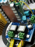
I experimented with the AVDD decoupling - adding a 5600uF cap in parallel with the 1000uF. The 'forwardness' on the violins went down, not completely away but a significant improvement. So I figured heroics would be needed on the AVDD. I built up a double-sided PCB with 14 * 1000uF FPCAPs around three of the edges and soldered it in position (with soldered supports either side) to allow easy bridging to the pads on the (now removed) C19. R19 had been previously removed. Now the forwardness is reduced again, practically gone but more listening is required to confirm. Very impressed with this little chip so far.
I experimented with the AVDD decoupling - adding a 5600uF cap in parallel with the 1000uF. The 'forwardness' on the violins went down, not completely away but a significant improvement. So I figured heroics would be needed on the AVDD. I built up a double-sided PCB with 14 * 1000uF FPCAPs around three of the edges and soldered it in position (with soldered supports either side) to allow easy bridging to the pads on the (now removed) C19. R19 had been previously removed. Now the forwardness is reduced again, practically gone but more listening is required to confirm. Very impressed with this little chip so far.
Attachments
- Status
- This old topic is closed. If you want to reopen this topic, contact a moderator using the "Report Post" button.
- Home
- Amplifiers
- Class D
- tpa3220: diy, evm-micro, UA801x-AL inductors, etc