This thread will be a build log of a TPA3136D2 based 20W PBTL mono amplifier with onboard bluetooth and a few other goodies.
I need a small camping/party amp that will play music at moderate volume, powered from a battery that should be enough for a 3 day camping trip.
I've been a software developer for 25 years and I am thinking about switching industries and finding a job in the embedded world. I don't have much profesional experience in that industry, so I want to use this project in job interviews as a demo of what I can do. Which is why I decided to do a little over-engineering. These are things I want to have on the PCB:
- CSR8635 bluetooth module
- TPA3136D2 amp in mono PBTL mode
- Battery over-discharge protection with a MAX6457
- Battery voltage and power consumption monitoring with an INA219
- An Atmel AVR microncotroller which comunicates with INA219 and outputs the values to a 7 sedment LED display
I am not interested in building a nice enclosure. I will just put the PCB in a hard transparent plasic tool box and drill holes for the battery input and speaker outputs. The least amount of work for a functional box.
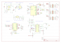
I have finished the first version of the schematic and the PCB. The PCB is a very rough prototype with crude layout, it will need more work. I should receive the boards in the next week or so. Can't wait...
I plan to assemble and test the prototype and maybe make a final PCB version with the bigger problems ironed out. I am sure I will have a few problems because I rushed the PCB layout a little.
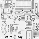
This will be the first white PCB I ordered, so decided to call it White boy
I will post more details in the next few days while I wait for the PCB. Meanwhile, you can check the project out on GitHub and open it with KiCAD v5: NovaBox and WhiteBoy
The schematic PDF: https://github.com/nodep/NovaBox/raw/master/docs/WhiteBoy.pdf
Thanks for reading, any comments are welcome!
I need a small camping/party amp that will play music at moderate volume, powered from a battery that should be enough for a 3 day camping trip.
I've been a software developer for 25 years and I am thinking about switching industries and finding a job in the embedded world. I don't have much profesional experience in that industry, so I want to use this project in job interviews as a demo of what I can do. Which is why I decided to do a little over-engineering. These are things I want to have on the PCB:
- CSR8635 bluetooth module
- TPA3136D2 amp in mono PBTL mode
- Battery over-discharge protection with a MAX6457
- Battery voltage and power consumption monitoring with an INA219
- An Atmel AVR microncotroller which comunicates with INA219 and outputs the values to a 7 sedment LED display
I am not interested in building a nice enclosure. I will just put the PCB in a hard transparent plasic tool box and drill holes for the battery input and speaker outputs. The least amount of work for a functional box.
I have finished the first version of the schematic and the PCB. The PCB is a very rough prototype with crude layout, it will need more work. I should receive the boards in the next week or so. Can't wait...
I plan to assemble and test the prototype and maybe make a final PCB version with the bigger problems ironed out. I am sure I will have a few problems because I rushed the PCB layout a little.
This will be the first white PCB I ordered, so decided to call it White boy
I will post more details in the next few days while I wait for the PCB. Meanwhile, you can check the project out on GitHub and open it with KiCAD v5: NovaBox and WhiteBoy
The schematic PDF: https://github.com/nodep/NovaBox/raw/master/docs/WhiteBoy.pdf
Thanks for reading, any comments are welcome!
Attachments
Last edited:
I plan to use a sealed lead-acid battery to power the circuit. I've found a cyclic duty gel battery rated at 35 Amp/hour, which I guess is about 440 Watt/hour. Should be enough to run the amp and also charge my phone.
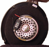
I don't want to build a speaker, so I will borrow one from a friend. He bought a cheapo powered speaker pair where one of the speakers contains the electronics and the other is just a box with the drivers and a handle. I tested that box with a TPA3116 board I got on ebay and it sounds amazing considering how cheap those speakers were. Much better than I expected. It has an 8 inch driver and two tweeters.
This is the speaker set (Fenton SPB-8):

The main driver has no markings. I've measured the total resistance at the input port and it showed 3.5ohm. I would have been happier with an 8 ohm speaker, but hey, beggars & choosers...
I will also have a DS18S20 digital thermometer on the PCB controlled by the microcontroller. Just another gimmick
Still waiting for the PCBs...
And just in case this is not obvious, I am a noob and I am mostly figuring this out as I do it, so comments are welcome.
I don't want to build a speaker, so I will borrow one from a friend. He bought a cheapo powered speaker pair where one of the speakers contains the electronics and the other is just a box with the drivers and a handle. I tested that box with a TPA3116 board I got on ebay and it sounds amazing considering how cheap those speakers were. Much better than I expected. It has an 8 inch driver and two tweeters.
This is the speaker set (Fenton SPB-8):
The main driver has no markings. I've measured the total resistance at the input port and it showed 3.5ohm. I would have been happier with an 8 ohm speaker, but hey, beggars & choosers...
I will also have a DS18S20 digital thermometer on the PCB controlled by the microcontroller. Just another gimmick
Still waiting for the PCBs...
And just in case this is not obvious, I am a noob and I am mostly figuring this out as I do it, so comments are welcome.
I am going that road for some time, i.e. TPA3118 and 12V/1.4Ah SLA. It is amazing how much power you can produce over many hours with an average power consumption of 0.1~0.2 amps. So I would expect 12V/6.5Ah would do over the weekend trip as well.
Meanwhile I swapped the SLA and use a pack of 4x18650 LiIon accus, giving 14.4V/2.2Ah: More power, less bulky!
Perhaps you have some accupack from a cordless drill or similar? In that case the appropriate charger is already at hand...
Meanwhile I swapped the SLA and use a pack of 4x18650 LiIon accus, giving 14.4V/2.2Ah: More power, less bulky!
Perhaps you have some accupack from a cordless drill or similar? In that case the appropriate charger is already at hand...
Last edited:
That is not a bad idea. However, a fully charged LiIon is 4.2V and 4x4.2V is 16.8V which is a bit more than the chip can take. The datasheet lists max recommended supply at 14.4V. Absolute max is at 20V, but I don't want to push it above recommended.
And bulk is not really a problem for me. The problem is estimating the battery capacity I need, and I will probably overshoot. I only get one charge, so at least 15 Ah, and more like 20-25. Better safe than sorry
I've tested the TPA3116 with a 6 cell LiPo battery at 25.2V. It was nice & loud The-neighbours-will-call-the-cops loud And that was only one 50W channel outputting around 20W with the CSR8635 configured to downmix stereo to a single mono channel.
Which is why I decided on to go with the TPA3136. It should be able to do 10W-12W without audible distortion in PBTL. I think that will be enough.
And bulk is not really a problem for me. The problem is estimating the battery capacity I need, and I will probably overshoot. I only get one charge, so at least 15 Ah, and more like 20-25. Better safe than sorry
I've tested the TPA3116 with a 6 cell LiPo battery at 25.2V. It was nice & loud
The-neighbours-will-call-the-cops loud And that was only one 50W channel outputting around 20W with the CSR8635 configured to downmix stereo to a single mono channel.Which is why I decided on to go with the TPA3136. It should be able to do 10W-12W without audible distortion in PBTL. I think that will be enough.
When 20V is max, 16.8 is ok to use.
Why not use a tpa3116 board? At lower voltage and higher ohm speakers it is just as efficient as it's low power brothers. You could use 2x12v and a simpel dpdt switch to switch from parallel to serial and back; giving you 12V eco mode which will run very long at lower volumes and a 24V power/ loud mode which will drain the battery 3 times less slow with the same volume as the in eco mode.
Why not use a tpa3116 board? At lower voltage and higher ohm speakers it is just as efficient as it's low power brothers. You could use 2x12v and a simpel dpdt switch to switch from parallel to serial and back; giving you 12V eco mode which will run very long at lower volumes and a 24V power/ loud mode which will drain the battery 3 times less slow with the same volume as the in eco mode.
Last edited:
I could use the tpa3116 board I already have, but where is the fun in that? My main reason for doing this is to learn something. The second one is that I really enjoy designing and building something from scratch. Well actually, from scratch would imply an amp with discrete components, but using a chip and designing a PCB around that is good enough for now. Another reason for tpa3136 is that I already have 9 of these chips at home. A few years ago I built a bluetooth speaker based on a pair of PAM8304, and two 10W Visaton drivers in a transparent toolbox, but that wasn't loud enough. So I thought I might make a more powerfull amp for these speakers and found tpa3136 on Farnell and ordered 10 of them. I used one on a very simple board (no bluetooth, no output filtering) which I did just to see if I can solder the heat dissipating pad. I knew I can solder 0.65mm pitched pins (even 0.5mm is not really a problem), but that pad was scary. And to my surprise, it was very straightforward. Good flux and a horseshoe soldering tip from the bottom of the PCB did the job. Actually, it was so much easier than I expected that it could be that I just got very lucky. I wonder if I will be able to pull that off again...
And then I saw the speaker at my friend's place and asked if I can borrow that for the camping trip. So I bought a tpa3116 board to see what I can expect out of that speaker. It sounded amazing (all things considered) and I decided to ditch the original plan and make a mono 20W amp out of the chips I already have.
I will probably put both the ebay tpa3116 and my tpa3136 board in a single box and then mix & match I have a 1.3Ah 25V LiPo battery that will power the tpa3116 if I need to go very loud, and the tpa3136 powered from the SLA battery for everything else. And the I could even use the SLA battery to reacharge the LiPo if needed. A little crazy, but who cares
My tpa3136 board will display the battery voltage, so I will be able to estimate how much power I have left in the SLA.
Thanks for the tweeter suggestion, I didn't know that.
My main reason for doing this is to learn something. The second one is that I really enjoy designing and building something from scratch. Well actually, from scratch would imply an amp with discrete components, but using a chip and designing a PCB around that is good enough for now. Another reason for tpa3136 is that I already have 9 of these chips at home. A few years ago I built a bluetooth speaker based on a pair of PAM8304, and two 10W Visaton drivers in a transparent toolbox, but that wasn't loud enough. So I thought I might make a more powerfull amp for these speakers and found tpa3136 on Farnell and ordered 10 of them. I used one on a very simple board (no bluetooth, no output filtering) which I did just to see if I can solder the heat dissipating pad. I knew I can solder 0.65mm pitched pins (even 0.5mm is not really a problem), but that pad was scary. And to my surprise, it was very straightforward. Good flux and a horseshoe soldering tip from the bottom of the PCB did the job. Actually, it was so much easier than I expected that it could be that I just got very lucky. I wonder if I will be able to pull that off again...And then I saw the speaker at my friend's place and asked if I can borrow that for the camping trip. So I bought a tpa3116 board to see what I can expect out of that speaker. It sounded amazing (all things considered) and I decided to ditch the original plan and make a mono 20W amp out of the chips I already have.
I will probably put both the ebay tpa3116 and my tpa3136 board in a single box and then mix & match
I have a 1.3Ah 25V LiPo battery that will power the tpa3116 if I need to go very loud, and the tpa3136 powered from the SLA battery for everything else. And the I could even use the SLA battery to reacharge the LiPo if needed. A little crazy, but who cares My tpa3136 board will display the battery voltage, so I will be able to estimate how much power I have left in the SLA.
Thanks for the tweeter suggestion, I didn't know that.
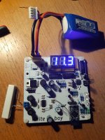
I've got the PCBs! Yay!
I've assembled the first prototype, and of course, there are bugs a-plenty. The biggest one is that I didn't connect the amp's AVCC to power I've just connected the decoupling 1uF cap between AVCC and GND but it has nothing to decouple. A botch wire fixes this.
The second problem is that I've miscalculated the resistors for the battery protection voltage divider, so that instead of cutting the power off at 11.2V it cuts it off at 10.4V. I've selected the wrong threshold voltage for the chip I got Not too big of a problem.
Then I've messed up soldering the AVR. I've started soldering it but then noticed it is slightly misaligned, and when I tried to move it I lifted a few traces off of the PCB. But, I've managed to fix that.
And btw, white soldermask kinda sucks. It sure looks nice, but it peels off too easily if heated up. Or maybe this was just a bad batch?
I am getting sleepy, so I will continue testing in the next few days.
I've assembled the first prototype, and of course, there are bugs a-plenty. The biggest one is that I didn't connect the amp's AVCC to power
I've just connected the decoupling 1uF cap between AVCC and GND but it has nothing to decouple. A botch wire fixes this.The second problem is that I've miscalculated the resistors for the battery protection voltage divider, so that instead of cutting the power off at 11.2V it cuts it off at 10.4V. I've selected the wrong threshold voltage for the chip I got
Not too big of a problem.Then I've messed up soldering the AVR. I've started soldering it but then noticed it is slightly misaligned, and when I tried to move it I lifted a few traces off of the PCB. But, I've managed to fix that.
And btw, white soldermask kinda sucks. It sure looks nice, but it peels off too easily if heated up. Or maybe this was just a bad batch?
I am getting sleepy, so I will continue testing in the next few days.
After a few more cut traces, botch wires and facepal moments, things are (mostly) working. The circuit sounds decent, but it is quieter than I expected. I guess 20W is not as loud as I thought. I might try to change the power supply and increase the voltage to 16V just to see what happens. Maybe it will release the magic smoke...
The chip is barely heating up. It is lukewarm after playing a 440Hz sine for a few minutes at just below clipping. This bottom pad soldering really does wonders.
I have a 4.7 Ohm 10W resistor as a dummy load, and I am playing the 440Hz sine wave into the load. The first three measurements are created with the ground clip and probe connected across the dummy load:


I guess this is nice, but things get a little more complicated when I connect the oscilloscope ground clip to my circuit ground, and two probes to the speaker outputs:


That 1.2V peak2peak noise is clearly the Class D switching frequency, and it is in phase which is why I didn't see it in the first batch, but this is where I need help: How can I figure out what is causing this? Is this even a problem?
I have unshielded coils and a 680nF 50V X7R capacitors at the output. Could that have something to do with this?
I have tried waves with lower frequencies (down to 55Hz) and the output looks similar to the 440Hz. I have not tried to go above 440Hz yet, I ran out of time, but I will check that too.
What else can I test? I don't have a spectrum analyzer, but I might try the FFT of my oscilloscope.
Thanks for reading and thanks for any help or comments!
The circuit sounds decent, but it is quieter than I expected. I guess 20W is not as loud as I thought. I might try to change the power supply and increase the voltage to 16V just to see what happens. Maybe it will release the magic smoke...The chip is barely heating up. It is lukewarm after playing a 440Hz sine for a few minutes at just below clipping. This bottom pad soldering really does wonders.
I have a 4.7 Ohm 10W resistor as a dummy load, and I am playing the 440Hz sine wave into the load. The first three measurements are created with the ground clip and probe connected across the dummy load:
I guess this is nice, but things get a little more complicated when I connect the oscilloscope ground clip to my circuit ground, and two probes to the speaker outputs:
That 1.2V peak2peak noise is clearly the Class D switching frequency, and it is in phase which is why I didn't see it in the first batch, but this is where I need help: How can I figure out what is causing this? Is this even a problem?
I have unshielded coils and a 680nF 50V X7R capacitors at the output. Could that have something to do with this?
I have tried waves with lower frequencies (down to 55Hz) and the output looks similar to the 440Hz. I have not tried to go above 440Hz yet, I ran out of time, but I will check that too.
What else can I test? I don't have a spectrum analyzer, but I might try the FFT of my oscilloscope.
Thanks for reading and thanks for any help or comments!
Attachments
That 1.2V peak2peak noise is clearly the Class D switching frequency, and it is in phase which is why I didn't see it in the first batch, but this is where I need help: How can I figure out what is causing this? Is this even a problem?
I have unshielded coils and a 680nF 50V X7R capacitors at the output. Could that have something to do with this?
Thanks for reading and thanks for any help or comments!
The 2nd order LC output filter reduces the carrier frequency, it does not eliminate it. 400KHz sent to the speaker cables will further reduce the content and the remains will not disturb your speakers. Not even your dog will be aware.
Very nice job!
Maybe get yourself some bat-tweeters 20kHz - 150Khz and do some serious testing/ animal torture........ lol
Maybe get yourself some bat-tweeters 20kHz - 150Khz
and do some serious testing/ animal torture........ lolThe 2nd order LC output filter reduces the carrier frequency, it does not eliminate it. 400KHz sent to the speaker cables will further reduce the content and the remains will not disturb your speakers. Not even your dog will be aware.
Oh, I know I can't hear it, and judging by the first measurement (the first three captures in my previous post) I am not really releasing anything other than the 440Hz sine wave into the speaker. But I can measure the switching noise between my ground and either of the speaker terminals. That is what the last three captures show. That noise is in phase with respect to the two speaker terminals so it cancels out.
What I want to know if I can do anything about that? I am guessing beefier power decoupling capacitors might help, but I didn't have time to check that yet. I currently have two 220uF low ESR caps on the power, I will try to double it.
Very nice job!
Maybe get yourself some bat-tweeters 20kHz - 150Khz
Thank you!
And thanks for the suggestion about the super tweeters, but I really love my dog, and I don't want to torture her And btw, has anyone heard these in action? Do they really do what they claim? It sounds a little far fetched:■ The tone quality is improved when you attach it to your speaker cabinet and connect it to the + and - terminals.
■ Music sound becomes more natural and realistic.
■ In TV sound comes speaking more realistically from the person’s mouth with 3D feeling.
■ Dull headphones are vividly revived.
Will the amp board ultimately live in the same enclosure as the speaker? In other words, do you expect a fairly short connection between the amp and the speaker? If so, you could consider doing away with the output LC filter and using a simple ferrite bead + capacitor filter. You've probably seen this already, but the tpa3136 datasheet talks about this on page 18, see section 10.2.2.1 "Ferrite Bead Filter Considerations". The DS suggests this is appropriate if the speaker cable length is 100cm or less.
My understanding is, having that carrier frequency on your output "shouldn't" have any audible impact. You mainly want to be a "good EMI citizen" and not pollute the environment with electromagnetic noise. With sufficiently short speaker cables, you naturally become less of a polluter. Ferrite bead + cap also has the advantage of being smaller (save PCB space) and cheaper.
On the other hand, you can add further filtering. Take a look at the tpa3116 datasheet, specifically page 26: the "Typical Application" Schematic (Figure 37). You can see that TI has the standard LC filter, but also a 1nF C to ground and 3R3+10nF RC filter, too. Most of TI's higher-powered class D amp chips have the extra filtering in the reference implementation circuit.
Another thing to think about, you probably already know this, but in case not: that LC filter is actually an LCR filter, where the "R" is your speaker. That's why the L & C values change depending on speaker impedance. But rarely (ever?) do speakers have a flat impedance curve, i.e. impedance is different at different frequencies. So when you decide on an "R" value for your speaker, you should think about what frequency you reference.
There are quite a few threads here talking about class D output filters. Here's one that's fairly short and readable: Some rambling calculation on TPA3116/8 filters.
I started to design a tpa3136 PCB a while ago. I never had it made. It wasn't anything special, basically just copied the reference implementation from the datasheet. Playing with the tpa311x amps is what got me into diyAudio. I've always had a special place in my heart for the tpa3110 in particular. Somewhere I got the impression the tpa3136 is the successor to the tpa3110, so I wanted to make a "tribute" amp. But I never finished that project.
If you get tired of the tpa3136, you might have a look at the tpa3220. That's probably the next class D chip I'll play with, as it's not too much more complicated that the tpa311x, but the measured performance is substantially better.
Hope some of this rambling nonsense is helpful!
Will the amp board ultimately live in the same enclosure as the speaker? In other words, do you expect a fairly short connection between the amp and the speaker? If so, you could consider doing away with the output LC filter and using a simple ferrite bead + capacitor filter. You've probably seen this already, but the tpa3136 datasheet talks about this on page 18, see section 10.2.2.1 "Ferrite Bead Filter Considerations". The DS suggests this is appropriate if the speaker cable length is 100cm or less.
The amp will be in a separate box, but the speaker cables should be shorter than 100cm. But regardless of EMI, the datasheet has this part about the LC filter and efficiency:
The TPA3136D2, TPA3136AD2 modulation scheme has little loss in the load without a filter because the pulses are short and the change in voltage is VCC instead of 2 × VCC. As the output power increases, the pulses widen, making the ripple current larger. Ripple current could be filtered with an LC filter for increased efficiency, but for most applications the filter is not needed.
An LC filter with a cutoff frequency less than the class-D switching frequency allows the switching current to flow through the filter instead of the load. The filter has less resistance but higher impedance at the switching frequency than the speaker, which results in less power dissipation, therefore increasing efficiency.
But I might make a 2x10W amp with this chip in the future, and PCB space will be an issue, so I might try the ferrite beads.
If you get tired of the tpa3136, you might have a look at the tpa3220. That's probably the next class D chip I'll play with, as it's not too much more complicated that the tpa311x, but the measured performance is substantially better.
Hope some of this rambling nonsense is helpful!
Very helpful, thank you!
And thanks for the links about those output filter calculations. Learning time And I will certainly make a more powerful amp. I still haven't decided between tpa3220 and tpa3128. tpa3220 is more interesting, simply because tpa3128 is more similar to tpa3136. By the way is tpa3128 a successor to tpa3118?. And what is the difference between tpa3128 and tpa3129 (other than the max output power)?
Back to my tpa3136, I have noticed that the output of the Bluetooth module depends on the source device. For instance, my Galaxy A8 can get the output to clip on the last two volume settings, but my older Galaxy S5 mini is quieter and doesn't get close to clipping even at max volume. That is for the same 440Hz test file I am using. So the next version of my amp must have selectable gain, which tpa3136 doesn't have (only fixed 26dB).
Another interesting thing I noticed is that I get a clicking sound after I pull the shutdown pin to ground and then release it. I made the firmware of the microcontroller turn the amp on and off every two seconds and I can clearly hear a click when it turns on. I haven't looked into this more, but it sure is interesting.
It needs less quiescent current, has lower RDS_on and works with lower supply voltage. If i remember correctly they also tweaked the 1SPW modulation a bit with adaptive level-shifting to save even more power. I did some PCBs in the past for it:By the way is tpa3128 a successor to tpa3118?. And what is the difference between tpa3128 and tpa3129 (other than the max output power)?
TPA3128D2 – 2 x 30/50W Stereo 60/100W Mono Class-D Verstarker – #360customs
Last edited:
........ @bat tweeters - And btw, has anyone heard these in action? Do they really do what they claim? It sounds a little far fetched:
No my hearing stops at about 15KHz, should have to ask my dog if they did.
Try to read this without laughing TAKET | user manual
Glad you can connect them with or without heatshrink and solder, in or on your tv and connect them to a line out of the tv......
And I love the headphone application
Yes, my fellow human doings.........
I tried feeding 16.8V to my amp. I didn't work. I am guessing it went into overvoltage protection because it would not turn on. It woke up for a moment when the voltage started dropping when I plugged out the battery. I don't have a bench power supply (any recomendations for a physically small one? less that 300EUR?), so I can't say exactly what is the overvoltage limit. I had to discharge my battery in steps to figure out at what voltage the amp starts to work. But it was somewhere between 15.5V and 15.8V
The INA219 power meter seems to work nice It measures battery voltage, average power consumption (in Watts), and total energy consumption (in Watt/hour). I was really surprised at how little power is drawn on average when it plays music. With supply voltage at 15.5V, and volume set around clipping, the average power consumption is about 3W. This seems so low, that it is possible I might be missing something. But the same circuit is reporting 20-22W of power draw for my test 440Hz sine wave at the same volume, which should be correct. So I guess the conclusion is that music is not a test sine wave, after all. I just didn't think the difference would be so large. The way I configured it, INA219 is sampling the power consumption every 0.5ms, then averaging that over 128 samples, and reporting that average every 68.1ms to the microcontroller. I might try less averaging, but I don't think that should matter much.
I want to make the energy consumption meter 'persistant'. Currently it starts from 0 on every startup, accumulates the Wh, and forgets the accumulated value when turned off. But I could save the accumulated Watt/hours every few minutes to the microcontroller's EEPROM, and read that value on every startup and just continue accumulating and saving. This could work as a crude battery gauge. I wonder how accurate, though?
I am making the final version of this circuit. It will have shielded coils (RFS1412) and film capacitors at the output filter Not that I've noticed any problem with my unshielded coils and X7R capacitors. I've changed the BT module to CSR8645 because I've noticed the CSR8635 module I used is quite noisy. I've also added 5 buttons to the module, and 2 buttons to the microcontroller. And I've added a USB-B connector to the BT module. The CSR chip can also serve as a USB sound device, so I am hoping to have an option to avoid all that nasty BT compression/decompression and use this as a wired amplifier and maybe get better sound. For this to work, the chip has to have a good DAC, so we'll see I've used a vertical instead of a horizontal USB connector. It was easier to route, and I have a few of these connectors at home. There could be a problem if the insertion force of the connector is large enough to warp the PCB and break connections, but I am using 1.6mm PCB, and those things are tough, so I think it should be fine.
I will also change the 3 LEDs connected to the BT module to a single diffused RGB LED. They look prettier.
Thanks for reading my ramblings
I am guessing it went into overvoltage protection because it would not turn on. It woke up for a moment when the voltage started dropping when I plugged out the battery. I don't have a bench power supply (any recomendations for a physically small one? less that 300EUR?), so I can't say exactly what is the overvoltage limit. I had to discharge my battery in steps to figure out at what voltage the amp starts to work. But it was somewhere between 15.5V and 15.8VThe INA219 power meter seems to work nice
It measures battery voltage, average power consumption (in Watts), and total energy consumption (in Watt/hour). I was really surprised at how little power is drawn on average when it plays music. With supply voltage at 15.5V, and volume set around clipping, the average power consumption is about 3W. This seems so low, that it is possible I might be missing something. But the same circuit is reporting 20-22W of power draw for my test 440Hz sine wave at the same volume, which should be correct. So I guess the conclusion is that music is not a test sine wave, after all. I just didn't think the difference would be so large. The way I configured it, INA219 is sampling the power consumption every 0.5ms, then averaging that over 128 samples, and reporting that average every 68.1ms to the microcontroller. I might try less averaging, but I don't think that should matter much.I want to make the energy consumption meter 'persistant'. Currently it starts from 0 on every startup, accumulates the Wh, and forgets the accumulated value when turned off. But I could save the accumulated Watt/hours every few minutes to the microcontroller's EEPROM, and read that value on every startup and just continue accumulating and saving. This could work as a crude battery gauge. I wonder how accurate, though?
I am making the final version of this circuit. It will have shielded coils (RFS1412) and film capacitors at the output filter
Not that I've noticed any problem with my unshielded coils and X7R capacitors. I've changed the BT module to CSR8645 because I've noticed the CSR8635 module I used is quite noisy. I've also added 5 buttons to the module, and 2 buttons to the microcontroller. And I've added a USB-B connector to the BT module. The CSR chip can also serve as a USB sound device, so I am hoping to have an option to avoid all that nasty BT compression/decompression and use this as a wired amplifier and maybe get better sound. For this to work, the chip has to have a good DAC, so we'll see I've used a vertical instead of a horizontal USB connector. It was easier to route, and I have a few of these connectors at home. There could be a problem if the insertion force of the connector is large enough to warp the PCB and break connections, but I am using 1.6mm PCB, and those things are tough, so I think it should be fine.I will also change the 3 LEDs connected to the BT module to a single diffused RGB LED. They look prettier.
Thanks for reading my ramblings
I have good experience with this one: CPS-3205 0-32V 0-5A Portable Adjustable DC Power Supply 110V/220V - US$54.99
Your power measurements seems correct. Music has a crest factor of 10dB+, which means 20W of music is really <2W average. This depends on the type of music and if you let your amp clip you also reduce the crest factor.
Its possible to make the consumption persistant, but don't rely on it as a gauge. Battery capacity changes over time, just rely on your voltage measurement.
- Status
- This old topic is closed. If you want to reopen this topic, contact a moderator using the "Report Post" button.
- Home
- Amplifiers
- Class D
- TPA3136D2 based amp