I am attempting to use some one of these 500W IRS2092 amplifier modules. I had some success with resistor loads (see the thread Ebay amp - is 500W believable?) but when I hooked up a real speaker I got sparks and smoke.
Some digging revealed that the fried component was a 10 ohm chip resistor R36, seen in this stock photo adjacent to the center screw terminal:

Strangely this seemed to only connect to another resistor, labeled R21, which was connected to ground. Checking a known good module confirmed R36 is indeed a 10 ohm resistor. However, after removing the fried R36 I found R21 was open. It didn't make sense to me to build two serial resistors across the load so I checked it with a capacitance meter and sure enough, 0.1 uF. So I believe these two components form the Zobel network from the IRAUDAMP7S
reference design.
For some reason I am getting a bunch of high frequency noise that those tiny components weren't designed to handle. Indeed, the reference design says:
Any ideas?
Edit: I forgot to mention that I had adjusted the carrier frequency down to 330 kHz to reduce load on output drivers. However, having now read through the reference design notes I found this:
Some digging revealed that the fried component was a 10 ohm chip resistor R36, seen in this stock photo adjacent to the center screw terminal:
Strangely this seemed to only connect to another resistor, labeled R21, which was connected to ground. Checking a known good module confirmed R36 is indeed a 10 ohm resistor. However, after removing the fried R36 I found R21 was open. It didn't make sense to me to build two serial resistors across the load so I checked it with a capacitance meter and sure enough, 0.1 uF. So I believe these two components form the Zobel network from the IRAUDAMP7S
reference design.
For some reason I am getting a bunch of high frequency noise that those tiny components weren't designed to handle. Indeed, the reference design says:
However, I confirmed there is a 330 ohm resistor connected to some small capacitor after the input capacitor. Presumably this is the 1 nF called for in the reference design so it is still unclear to me is what is causing the oscillation in the first place."The Zobel network is not thermally rated to handle continuous supersonic frequencies above 20kHz.
These supersonic input frequencies can be filtered out by adding R2 and C2 as shown on main schematic Fig 33 and Fig 34. This RC filter works also as an input RF filter to prevent potential radio frequency interferences."
Any ideas?
Edit: I forgot to mention that I had adjusted the carrier frequency down to 330 kHz to reduce load on output drivers. However, having now read through the reference design notes I found this:
Hmmm... maybe messing with the frequency wasn't a great idea. However, I also found this:"A single stage output filter can be used with switching frequencies of 400 kHz and greater; a design with a lower switching frequency may require an additional stage of LPF."
So since I want to drive two of these in a bridge configuration, should I set them both as close as possible to the same, or make one higher one lower? Would 385/415 kHz be a reasonable combination?"Normally, when adjusting the self-oscillating frequency of the different channels, it is suggested to either match the frequencies accurately, or have them separated by at least 25kHz. Under the normal operating condition with no audio input signal, the switching-frequency is set around 400kHz in the IRAUDAMP7S."
Last edited:
Mutual interference will tend to synchronize the channels, so if the channels are wired for BTL adjust frequency to same value. R36 SMD 10 ohms 1206 is a big no-no, normal 1206 SMD resistors have very limited overload capability, even special SMD resistors (very low value) have inferior overload capability compared to a simple 3W wirewound. Use a 3W wirewound.
Good advice, thanks. I have replaced the R36 SMD with a 1 W resistor since I could get those readily. Admittedly this isn't as good as a 3 W but if I watch it carefully for oscillation I can keep them from burning up before cut the power. I still need to be quick though because it takes literally a second for even the 1 W resistors to get hot enough to start to smoke once oscillation starts. I fear for the little chip capacitor "R21" also, as running a few amps through it would presumably cause it to fry quickly.
Unfortunately that is all the "effect" but I still haven't been able to eliminate the "cause": oscillation when these amplifiers are connected to an inductive load.
I also tried to be a bit more diligent with grounds: keeping the input and the load isolated (no ground loops) but still the amplifiers want to oscillate. I captured this in the moment before I killed the power and it looks like it is full power, 970 W @ 48kHz:
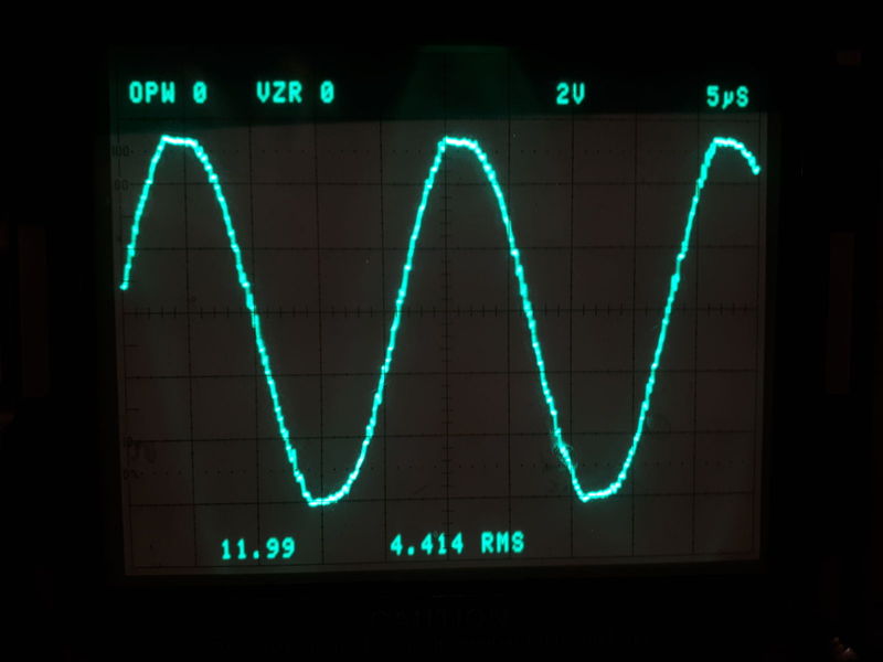
This was captured with the inputs grounded.
I am thinking perhaps increasing C2 to lower the frequency of that low-pass circuit but that seems like a bandaid to what is another issue.
Any other ideas what to try next?
A sustained oscillation requires feedback. There are two types of feedback paths to investigate.
One is direct path through IRS2092 self-oscillation network, like wrong parts. I recommend measuring these parts and posting a schematic. Improper part choice can lead the circuit to oscillate wrongly with anything but a resistive load at HF. The RC damper provides the resistive load at HF. The 100nF on the output damper RC seems a too low value, more usual value is 470nF, as much as LC output capacitor. A usual problem with ceramics is runout of capacitance as voltage approaches maximum, it must be a X7R 50V type at least, capacitance at ~50V can be measured with the help of a power supply, but requires extreme care to not damage capacitance meter, pre-charging the capacitor with a resistor then connecting the meter.
Another is indirect path, as ground loops. 50Khz is too low to be very effectively filtered by a simple input LPF network with low attenuation at 20Khz, -3dB @ 50Khz at best. However, 50Khz happens to be the usual resonant frequency of the LC filter. But there should not be 50Khz current flowing through ground terminals.
I was thinking the same thing about feedback, so last night I started going through the reference design schematic and mapping the component labels, concentrating on the feedback loop. I replaced the actual component numbers in green but when I got to R13 (R7 in the reference design) I found what could be causing my issues:

R13 should have been about 3.1K but was 100 ohm! Since everything else I found lined up with the reference design I would think that was a manufacturing error.
Anyway, I found some 1/4 W axial 3.1K resistors and will try soldering in a couple of those and see what happens.
Regarding the Zobel capacitance, the IR design does use 100 nF so I am guessing they just copied that.
I successfully replaced the incorrect 100 ohm resistor R13 with a 3.1K ohm (mine actually measured 2.95K) 1/4 W axial resistor and everything is working great. The amplifiers no longer oscillate whether connected to a resistive load, inductive load (real speaker) or no load at all.
Hopefully anyone else who purchased these incorrectly built amplifiers will benefit from this:

Hopefully anyone else who purchased these incorrectly built amplifiers will benefit from this:
jssidall, thanks alot for posting your finds. I'm in the middle of a sub project where I use 4 of these little boards. 1 per each 150W 8" subwoofers. I will be checking the R36 and R13 values today and report back.
1 question tho: is the mod to R36 still required after fixing R13 to 3K?
1 question tho: is the mod to R36 still required after fixing R13 to 3K?
")
I finally got around to replacing R13 with a 3.01K resistor in a 0603 package. I believe the 0805 package was the original size. Anyway, they work! Fans come on, amps are running very cool. Fans still running... I am using 2 500W +/- 65V SMPS to power 2 IRS2092S 500W boards each. During power up, there is no thump. Also, I use miniDSP 2x4 kit with miniDIGI for optical input and 4 RCA outputs direct into each of these IRS2092S amps for my 8" subs.
Trying to achieve more output by EQ using miniDSP. Very pleased so far! Thank you for this thread and for the OP posting his findings!
A sidenote: I measure the 1 SMPS at +74V/-60V and the IRS2092S amps did not seem to object, they worked fine... The other SMPS was measured at +-66V, no problem there...
Last edited:
I have ordered this
IRS2092S 500W Mono
IRS2092S 500W Mono Channel Digital Amplifier Class D HIFI Power Amp Board Digital Amplifier Module High Quality 2019 New-in Instrument Parts & Accessories from Tools on Aliexpress.com | Alibaba Group
1000W LLC Soft Switching Power Supply Board DC +65V 0V -65V
Details about 1000W LLC Soft Switching Power Supply HiFi Audio Amplifier PSU Board DC50V 80V for choose-in Amplifier from Consumer Electronics on Aliexpress.com | Alibaba Group
UPC1237 Dual Channel Speaker Protection Circuit Board DC 12-24V Boot Mute Delay
UPC1237 Dual Channel Speaker Protection Circuit Board DC 12-24V Boot Mute Delay | eBay
0805 SMD 1/4W 3kohm Tolerance:5%
100Pcs 0805 SMD 1/4W 0R ~ 10M chip resistor 0 10R 100R 220R 330R 470R 1K 4.7K 10K 47K 100K 0 10 100 330 470 ohm-in Resistors from Electronic Components & Supplies on Aliexpress.com | Alibaba Group
Is the resistance that is right?
Try the amplifiers before replacing the resistors?
The power supply is a 1000w, should it be 2x500w?
Is it necessary to install a Fuse before the power supply is plugged in?
5A 250v is okay?
before the input of the current to the amplifiers what Fuse to put?
I've noticed that a majority of these 500w boards handle a sudden transient spike of the input signal without a problem. Some others, however, temporarily mute themselves for a second. Seemed like a bus pumping symptom, but increasing the capacitance of the two 470uf 80V caps didn't remedy this. Just wondering why this only occurs on some boards but not others. 🤔
I've noticed that a majority of these 500w boards handle a sudden transient spike of the input signal without a problem. Some others, however, temporarily mute themselves for a second. Seemed like a bus pumping symptom, but increasing the capacitance of the two 470uf 80V caps didn't remedy this. Just wondering why this only occurs on some boards but not others. 🤔
I know exactly what are you talking about, I have the same problem, anyone solved this? I have two boards and one has this problem, idk, maybe preamp, I think only preamps are different in my case, same psu, same boards ( at least they look the same)
I successfully replaced the incorrect 100 ohm resistor R13 with a 3.1K ohm
Did you also replace that 10 ohm with something more powerful?
This resistor seems 1812 but 0.75W power seems very low. If this little one replace to 2512 which can withstand 2W, could that be enough? Or it is better to use a 3W or 5W metalfilm THT? A wire resistor is probably not a good choice if the resistance element is wounded form? I am thinking of inductance.
Or is it work too?
I was thinking the same thing about feedback, so last night I started going through the reference design schematic and mapping the component labels, concentrating on the feedback loop. I replaced the actual component numbers in green but when I got to R13 (R7 in the reference design) I found what could be causing my issues:
R13 should have been about 3.1K but was 100 ohm! Since everything else I found lined up with the reference design I would think that was a manufacturing error.
Anyway, I found some 1/4 W axial 3.1K resistors and will try soldering in a couple of those and see what happens.
Regarding the Zobel capacitance, the IR design does use 100 nF so I am guessing they just copied that.
Oh thank you so much, I wish I've come across this sooner as I was about to send it back to the seller!
There's no hiss now though I still have a 2Vpp 400khz carrier on the output. Is that a safe amount for tweeters to handle? I haven't replaced the Zobel components as it didn't fry as it did with other units.
Cheers,
Alex
2 Vp-p is 0.7 Vrms, so using ohms law, into an 8 ohm tweeter, that works out to 0.7^2/8 = 62 mW. So yes, perfectly safe.
Thank you for the explanation!
Cheers,
Alex
- Home
- Amplifiers
- Class D
- Fixing [and preventing] a fried Zobel network