See on the transformer's label, if the phases are pointed.
If not, then measure the transformer secondaries' phases, when the secondaries are disconnected and then use resistor dividers, if your oscilloscope can not handle 24Vrms.
You need two channel oscilloscope, to determine the both phases.
If not, then measure the transformer secondaries' phases, when the secondaries are disconnected and then use resistor dividers, if your oscilloscope can not handle 24Vrms.
You need two channel oscilloscope, to determine the both phases.
Sorry for the long delay in my answer. You know Christmas happened..
I do currently not own a 2 channel o-scope so I cannot check the phases of the coils...
But what I did do was to switch around the connection points of the two secondary coils to find the correct configuration. No of the options gave less hum on the output of the amp.
Any other ideas for the cause of this? Or is it just bad PCB layout?
................
My board did not came... Waiting for refund...
Sorry to hear that you did not get yours. I was lucky this time.
However, a bit later i ordered an XH-M590 board (TPA3116 based) and the seller sent it as a tracked letter. The tracking appeared to work and I was even told that it had arrived at the local mail office (not usual). Then strange things started to happen. I was told by the tracking information that a first attempt of delivery had failed (it had to be put in my mailbox with other things I received that day) while I was at home. The day after, the tracking information claimed that delivery was successful while nothing had arrived! I have 100% confidence in my mail-man and the stated delivery time was hours outside of his regular passage. I also did not receive the usual E-mail request to confirm receipt.
It is like somebody else than the mail-man/woman can manipulate the status of the tracking. For the time being the local mail carrier is investigating.
Though I receive far the majority of things I order, this kind of fake tracking is worrying. Wasn't the idea with tracking that I would know the real status?
Watch out for similar fake tracking and report it to your local mail carrier for investigation.

Last edited:
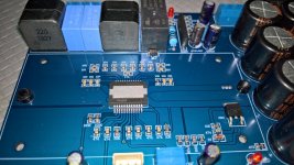
Finally my board arrived
The output filter is 22uH + 220nF, but the capacitor should be 470nF, according the datasheet!
Before the first power-up, I soldered 1.5k resistors at the outputs, before the relay contacts and 100nF capacitors in parallel of the 220nF.
The volume pot is 50k! It should be 10k...
There is little white noise, heard in the high frequency drivers, but at very close distance.
My transformer is 2x21-22V AC, which gives about +/-28-30V DC at the filter capacitors.
The 5V line is derived from a zener diode and transistor, which do not touch the heatsink!
There was white termal paste on the chip. I cleaned it and put Arctic Silver 5 paste for CPUs
At idle the heatsink and the output inductors are little warm. Not tested yet with strong signal.
The switching frequency is set to 340kHz.
Attachments
Last edited:
Finally my board arrived
The output filter is 22uH + 220nF, but the capacitor should be 470nF, according the datasheet!
Before the first power-up, I soldered 1.5k resistors at the outputs, before the relay contacts and 100nF capacitors in parallel of the 220nF.
The volume pot is 50k! It should be 10k...
There is little white noise, heard in the high frequency drivers, but at very close distance.
My transformer is 2x21-22V AC, which gives about +/-28-30V DC at the filter capacitors.
The 5V line is derived from a zener diode and transistor, which do not touch the heatsink!
There was white termal paste on the chip. I cleaned it and put Arctic Silver 5 paste for CPUs
At idle the heatsink and the output inductors are little warm. Not tested yet with strong signal.
The switching frequency is set to 340kHz.
I am happy to hear that also you got your board.
The 1K5, is that to give a minimum loading during start-up?
I haven't removed the heatsink (yet). Is the 5V for the relay circuit?
My tweeters may not be as efficient as yours or my ears are simply not as good as yours - I recall no white noise.
Good luck with it!
Yes, the 1k5 resistors are for the minimum loading during the start-up.
The 5V supply is for the Mode pin of the TDA8954 chip.
I use pro speakers, which are with 94-95dB/W sensitivity.
These days, after work, I'll try to make some measurements with the scope.
And there is big switch-off bump in the speakers. On switch-on the relay is properly delayed and there are no problems.
Last edited:
I just ordered a +-30V dual power supply for the XH-M252. Have not yet bought the XH-M252. Is this voltage pushing it too far..?
I was hoping you could recommend me an amp suitable for +-30V that fits in a car and costs ~$50.
power supply: 1000W Car Amplifier Boost Power Supply / DC to Dual DC Boost Power Supply / 12V 24V Car Amplifier Boost Board|Amplifier| | - AliExpress
I was hoping you could recommend me an amp suitable for +-30V that fits in a car and costs ~$50.
power supply: 1000W Car Amplifier Boost Power Supply / DC to Dual DC Boost Power Supply / 12V 24V Car Amplifier Boost Board|Amplifier| | - AliExpress
I just ordered a +-30V dual power supply for the XH-M252. Have not yet bought the XH-M252. Is this voltage pushing it too far..?
I was hoping you could recommend me an amp suitable for +-30V that fits in a car and costs ~$50.
power supply: 1000W Car Amplifier Boost Power Supply / DC to Dual DC Boost Power Supply / 12V 24V Car Amplifier Boost Board|Amplifier| | - AliExpress
Hi
if you look at the datasheet your voltage is ok +/-30V rail Voltage.
Table 11 page 21. look at the voltage of these tests its +/- 41V rail. again look at the datas of R4ohms - THD 0,5% (not at 10%) .
everything is fine
chris
I was hoping you could recommend me an amp suitable for +-30V that fits in a car and costs ~$50.
Why you don't buy an used car amplifier?
See my post #65 what should be added/modified at least for this module.
+/-30V supply is OK for this module.
Why you don't buy an used car amplifier?
See my post #65 what should be added/modified at least for this module.
+/-30V supply is OK for this module.
How confident are you with your changes being an improvement to what the manufacturer decided on?
I decided in the last minute to change the order of the power supply, set it to +-65V instead of +-30V.
Instead of the XH-M252 I opted for two of these IRS2092S, because they are more popular and perhaps gives higher volume (?): IRS2092S 500W Mono Channel Digital Amplifier Class D Hifi Amp Power Board With Fan Finished Product / Mono / Super Lm3886|Power Tool Accessories| | - AliExpress
Just tested this amp. No switch noise from fan. No hum or hiss. Using with 25V 250VA Avel Lindbergh trafo. Using 10R and double diode GLB between earth GND and center tap GND. Tested on 90dB speakers and could barely hear any noise or hum with ears pressed to speaker come.
Fan noise is loud. Could add a power resistor or string of diodes to drop speed. Does not need to be this fast.
Tested on 82dB multi-way speakers and definitely a lot of power for bass kick drums.
Fluke 101 measured 200uV rms noise at output. About 50mV DC offset.
Hi could you post a small diagram or picture of how you used the earth ground and amp ground to kill noise? i get lots of hum with this amp and my toroidal center taps are going only to the amp gnd terminals. i dpnt wanna blow nothing up so how is the 10 ohm resistor and 2 diodes tied together between the center tap amp/toirodal grounds and earth ground? btw im using a 300va dual 24v ac transformer. please excuse my newbie buttarse but i just get stuck on some things.
Hi All,
Taco5000, im very sorry for my poor name choise...
Nevertheless, i have bought an X-M252 Amplifier, and im getting some horrible noise from it...
I have tried alot, to no avail..
The noise im getting from the amplifier is a 200Hz hum. (This is measured with my phone close to the speaker)
The setup im using is a toroidal transformer (24-0-24), and a pre-amplifier (See below)
NE5532 OP-AMP HIFI Preamp Preamplifier Volume Tone EQ Control Board Module HighQ | eBay
The hum is originating from the amplifier, but it is quite low when only the amp is connected to a speaker.
As soon as i connect an input to the amplifier, the noise/hum gets louder. When the pre-amplifier is connected, to the amp, the noise is at its worst (compared to just RCA connectors directly into the amp). The noise hits its highest, when the volume pot on the pre-amplifier is turned all the way down. When i turn the pre-amp up to half volume, the noise is at it's lowest.
All wires to and from the amplifier & pre-amplifier are twisted to keep out noise (as much as possible).
I have created a DC-Filter to the mains, just before the transformer. This helped a bit on the hum.
It is also worth mentioning that i can hear my transformer hum when i place my ear next to it. It is not that loud though.
Can anyone point me in a direction? I'm all out of ideas of what to test next..
Best regards
No way. I have the exact same problem and took the same countermeasures. If anyone related to this can still give feedback on a cure I would be grateful. I even have the exact same preamp.
Last edited:
I compared this TDA8954 board with a generic TPA3255 board and the TPA definitely wins in quality of the sound
The TDA will be used in BTL mode for my oldschool Cervin-Vega! Vega124 subwoofer with power rails +/-30V.
The speaker is 4ohm and I hope to not burn the chip
At these supply voltages the max unclipped power in BTL into 4ohm is about 400W -> 10A R.M.S., or 14.42A Peak. I will not use it at that levels, so I think the board will be OK.
Also I have to modify the PCB for the BTL operation and I will make some lay-out improvements.
All will be described here, when it's done.
I pulled the trigger on the XH-M252 board about 5 to 6 months ago for a cheap thrills rig for work. Industrial production environment, listen as loud as I want with earplugs, as long as no excessive profanity content. Cheap, durable and loud were the goals. This board has them in spades.
The front end of the rig is a 10 dollar Bluetooth speaker module with line outputs. Next link in the chain is a parts express DSP kernel board and a 2 input 3 output board. Both drawing power from a USB cellphone charger. The DSP is setup as a parametric EQ and 2 way crossover, running into the XH-M board.
I didn't modify the amp board at all, just put a little little computer fan on it for cheap insurance. Also running off the USB charger for quiet factor. Sound blasters are the front panel of an old Peavey impulse PA speaker. Previous owner refused a repair on the plate amp and took the back shell to try to find a cheaper. Never came back.
I originally ran the board with big ol' hunks of iron on the bench. Couple of industrial control transformers. I found that the amp board never drew more than about 400 watts peak max from the wall, and usually around 150 watts continuous, maybe 300 peak at reasonable distortion figures. Not wanting to lug around a boat anchor of iron, I ordered up a pair of 36VDC, 6 Amp SMPS modules.
Gotta run, stay tuned for part 2
Ok back from the weekend activity. The speaker drivers are wired straight to the amp board, one per channel. Mid-woofer is a 4 ohm black widow, mid-high is an 8 ohm Peavey rx22 on the factory horn. Actively crossed over around 1700 low pass on the 12 and 1900 on the CD. The SMPS are wired in series and the outputs (+v, common, -v) go straight to the amps (24v, common, 24v).
Once the thing was assembled, I started it out running moderate power and roughly matched driver levels and crossover points using arta software and a measurement mic. Sounded great, so I pushed it and pushed it up and up in volume. Eventually I ran into over current protection with the 12. Kill a watt meter says 220 VA, 200 watts at the wall, continuous sine wave wave input using my phone over Bluetooth. No clipping. Audible distortion kicks in around 240w and I can squeeze almost 260w out of it before the protection kicks in.
I turned the rig down to the 200ish watt range, then began fiddling with auto EQ and fine tuning crossover points. The unit has been blasting out 120 dB music for months. No problems out of the amp board or the SMPS modules besides wires rattling loose at first. The thing just slaves away for 40 plus hours a week.
If I really really cared about the Peavey compression driver I would. Due to the mid-scooped voicing of the original unit, I decided not to put anything in between the chip amp and driver. Having nothing but wires allows me to twiddle and tweak the DSP EQ every once in a while to refine the sound. Besides the fact that the CD is 10+ dB more efficient than the 12 (so 1/4 or less input power), it has a good deal more 2nd harmonic distortion at high volume. Not trying to introduce phase distortion down by the crossover point, either.Did you put a series capacitor to the high frequency driver?
With a bigger value, than for the crossover frequency. Just for protection of HF driver.
Actually, the devil on my shoulder has encouraged me to put the Peavey CD out of it's misery after its decades of service. However, a better replacement driver hasn't fallen into my lap yet, and a new one would likely exceed the cost of the rest of the unit. At 8 ohms, this chip amp doesn't really have enough power to cook the driver unless it was crossed over way below below the range where it sounds good. Yes, if I clipped the output hard, it might be able to, but I would have to crank it up and walk away.
One year update on the xh-m252 beast.
After completing the Bluetooth frankenspeaker, I ended up just leaving it at work. Too big to lug around needlessly, plus coworkers were asking to use it on other shifts (cuz it's sooo loud and proud). Eventually someone did something to hang the DSP crossover and it obliterated all. Loud and unnatural noises going where they shouldn't. Upon autopsy, the channel feeding the compression horn opened up it's filter chip caps and the one TDA chip went brain dead. So guess what happened next...
I simply disconnected the DSP kernel board from the signal chain and rigged up a coil to the woofer, capacitor to the compression driver. Spare parts crossover is a something mh air core inductor and a big red m80 polywhatever film cap. First order, about the same crossover points as before.
I connected the left and right preamp outputs both to the good channel and replaced the filter caps and chip resistors with the real things: green chicklet mylar film caps and half watt metal film resistors. Jumped out one bridge rectifier and ran +V and -V into the empty PCB holes. Left the ground wire in the screw terminal and put it back in service.
The thing continues to belt out the loud noises, probably close to 20 hours a day. Unit sounds much better with the film caps in the output filter than before with the ceramic multi layer micro cheapies. No fans, no Uber HiFi extras, nothing. I was thinking about padding down the compression driver, but it's literally an earplug drill. Everybody and their brother uses some kind of bass enhancement EQ with the phone apps, so it is a trivial thing if you are listening without earplugs. The only thing that can keep up with it is a coworker's JBL partybox that cost him 650 dollars (double 10 WTW setup). With the mega bass enabled, it can edge out mine. Then here comes the foreman with a frowny face and a noise complaint...
- Home
- Amplifiers
- Class D
- TDA8954TH - XH-M252 board - anyone?