I would like to build the same concept CORRECTLY with preamp and switchable 8/4ohm outputs, toroidal or linear power, and a decent enclosure. Maybe even a headphone circuit. 3118 or better chips? Is there already a setup I could look at and copy crucial parts?
One could do Far worse than download the chip makers ' Spec ' sheet.
Then Build the exact circuit suggested.
Makers Do know what to do with Their products
") .
.One could do Far worse than download the chip makers ' Spec ' sheet.
Then Build the exact circuit suggested.
Makers Do know what to do with Their products
Thanks for the “duh” reply. I was thinking more of the full design before and after the implemented chip board.
Hey all TPS3116 fans,
I'm about to build a 2 way active amp. 'Bought the "SODIAL XH-M544" from amazon.de - what I liked about this board is that it is not too densely populated and all SMD parts are 0805 at least.
I'll drive all the amps balanced, 'glad to find out that the turn-on/off-pop is completely missing in that configuration. I'm also experimenting with input transformers that I had on hand... will be driven by balanced source as well.
I modded the boards to comply with my speaker setup, LF will be Dayton RS225-4 while the HF will be Sica LP 110.28/380 TW.
Cheap 'lytics were replaced by Chemi-Con PSG series.
Amplification is set to 20dB and all boards will be run in master mode.
Whats funny is that these boards stay completely cool, while another amp of mine (Sanwu TPA3118 2.1) heats up like crazy, all amps powered from 19,5V laptop brick)
The amps will be fed from ADAU1701 that are I2S input. I'Ve not settled about the output format to the amps, either standalone DACs or balanced driven by the ADAU DACs (balanced in DSP SW).
Will report back once I'm done with all that stuff.
Cheers!
edit: I'm in doubt about the parallel/series connection that I did on the output inductors, If one has some insight about putting exactly this type of inductors in parallel/series I'd appreciate that.
Attachments
Last edited:
I bought 3 switchmode power amp boards from Parts Express here in the U.S., after reading reviews, so I could build a great little boom box for camping trips or whatever. Although the reviews for all 3 boards were very positive, 2 of the three performed horribly on the test bench. The 3116 chip was on the one good board of the three, but also on one of the bad boards. For more details, check out my boombox project on my hobby website, at: ephaseaudio.com
I bought 3 switchmode power amp boards from Parts Express here in the U.S., after reading reviews, so I could build a great little boom box for camping trips or whatever. Although the reviews for all 3 boards were very positive, 2 of the three performed horribly on the test bench. The 3116 chip was on the one good board of the three, but also on one of the bad boards. For more details, check out my boombox project on my hobby website, at: ephaseaudio.com
Hi Bob,
You seem to have better gear than I and lengthy experience. I will only give you a few ideas for possible inspiration.
Many cheap TPA3116 boards have insufficient power line decoupling. I typically use 10000uF at the amplifier power supply terminals for extra decoupling. It may be exaggerated but rather too much than too little. I see you use a power converter (step-up I assume) before the amplifier. Such a converter often has little output buffer capacitance.
Did you try the poor amplifiers in a configuration that normally works: A 19V laptop charger with at least 2200uF before the amplifier power terminals?
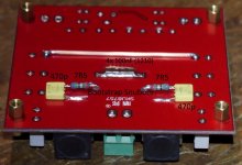
For your power measurements I guess you use dummy-loads. May they be inductive (from a photo I see wire-wound power resistors).
I do not see the poor TPA3116 boards. I have tried several very cheap TPA3116 boards and normally they function quite well with a bit of modifications.
Last edited:
Hey all TPS3116 fans,
...
Whats funny is that these boards stay completely cool, while another amp of mine (Sanwu TPA3118 2.1) heats up like crazy, all amps powered from 19,5V laptop brick)
...
TPA3118 rely on the bottom pad of the IC to transfer heat to the circuit board.
If this is not implemented very well then the IC does heat up quite quickly.
Whats funny is that these boards stay completely cool, while another amp of mine (Sanwu TPA3118 2.1) heats up like crazy, all amps powered from 19,5V laptop brick)
Do the chokes also heat up? If so, it is likely that the carrier frequency of the chip is wrong. None of my TPA3116/18 boards heat up. One did and that was because the gain/mode setting was wrong and the carrier frequency became some 130KHz.
Do the chokes also heat up? If so, it is likely that the carrier frequency of the chip is wrong. None of my TPA3116/18 boards heat up. One did and that was because the gain/mode setting was wrong and the carrier frequency became some 130KHz.
yes, the chokes also heat up, thats why I've fitted the green heatsinks. Thanks for the hint, will check the config.
edit: OK, easier said than done, I've got the weird behaviour to mold things into epoxy once I've found them to work. Well, that will be a massacre
Last edited:
TPA3118 rely on the bottom pad of the IC to transfer heat to the circuit board.
If this is not implemented very well then the IC does heat up quite quickly.
I'd exclude that. The mono boards (TPA3116) stay completely cool with the copper plate only, I guess they do not even reach more than 35°C while the Sanwu 2.1 board (TPA3118, GND plane vias have been resoldered + xtra heatsink on top) heats up to ~70°C. I guess I can trust "FalscherFranzose" aka FauxFrench in his diagnosis.
Last edited:
I have absolutely abused, even put mismatched and low impedance loads on the Lepai 2020TI 3118 chip in the Arizona summer and it has gone into protection at clipping (I’m assuming without measurements) but has never got hot amazingly. I played it LOUD for hours on 19v power, but the supplied 12v is plenty for normal bedroom use. So there is something to be said about implementation - there’s really nothing to this board.
Hi Bob,
You seem to have better gear than I and lengthy experience. I will only give you a few ideas for possible inspiration.
Many cheap TPA3116 boards have insufficient power line decoupling. I typically use 10000uF at the amplifier power supply terminals for extra decoupling. It may be exaggerated but rather too much than too little. I see you use a power converter (step-up I assume) before the amplifier. Such a converter often has little output buffer capacitance.
Did you try the poor amplifiers in a configuration that normally works: A 19V laptop charger with at least 2200uF before the amplifier power terminals?
For your power measurements I guess you use dummy-loads. May they be inductive (from a photo I see wire-wound power resistors).
I do not see the poor TPA3116 boards. I have tried several very cheap TPA3116 boards and normally they function quite well with a bit of modifications.
I was using an actively regulated power supply that should have had a near zero source impedance, but also added a big Electrolytic, probably about 10kUF just to be sure. The cap is especially necessarily needed if the amp brd. will be powered by battery. As a battery discharges, it's source impedance goes up significantly, which often causes an amplifer to oscillate, and/or have problems with overdrive. That can lead to speaker burnout. I also added 0.1uF ceramic caps to the amp board right where the power supply comes in, as one more precaution. Most amplifier circuits of any type need to see a very near zero ohm source impedance in the power supply, especially at very high frequencies (to at least 1mHZ IMO), or the phase margin issues get thrown way off, and oscillation results.
You can, too low clock frequency is the most probable fault imho.I'd exclude that. The mono boards (TPA3116) stay completely cool with the copper plate only, I guess they do not even reach more than 35°C while the Sanwu 2.1 board (TPA3118, GND plane vias have been resoldered + xtra heatsink on top) heats up to ~70°C. I guess I can trust "FalscherFranzose" aka FauxFrench in his diagnosis.
Revisiting this. Tried both amps with 24v 3A power brick on 3” 4ohm speakers. I need more power and even with a dual NE5532P preamp the performance isn’t much better than straight from an iPod.
Can somebody post a schematic or link to a diagram showing a proper decoupling cicuit with 10kuf caps with is dual amp single power brick scenario? I want to do it correctly.
Can somebody post a schematic or link to a diagram showing a proper decoupling cicuit with 10kuf caps with is dual amp single power brick scenario? I want to do it correctly.
Total newb, no o-scope, laptop with all my measuring software took a hard dive. All that I have is a cheap DMM, a trusty old Weller and new LED lit solder iron. Oh, and lots of raw speakers and electronic components. May be in the wrong place, but electronics was what I originally wanted to do instead of medicine or telecom. I built speaker enclosures and full car installations, did live sound and home theater, and built stomp boxes and chip amps for guitar, bass and mobile DJ setups. I’m disabled with limited movement and it gets very boring with a lot less income. I have memory issues, so I apologize if I keep asking the same questions.
Still learning...thanks for the help!
I plan to run mostly 4Ohm loads, but some 8ohm speakers also.
Still learning...thanks for the help!
I plan to run mostly 4Ohm loads, but some 8ohm speakers also.
Last edited:
Well, without measuring your output power you are fishing in muddy waters.
I realize that and the 10kuf value always seemed high. The boards already have filters. The “crest factor” does seem like it would come into play sooner or later. I can only measure just short of full gain or whatever these trimpots are there to do, but there seems to be a hum introduced if not at full travel or too low to be effective.
I’m just going by what fauxfrench suggested, with using a bigger current with both amp boards. It seemed what I was looking for when I was thinking about purchasing two 3118 boards, but I already had two 3116 boards I bought for $4 each after seeing johnaudiotech review the exact same boad. I also have Two decent 2.1 dual 3116 boards that actually perform and measured well, but they both have noisy Bluetooth.
I can only measure the outputs with a multimeter.
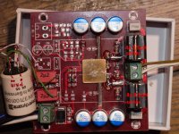
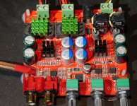
Recently I had to test a 24V SMPS for continued operation after repair. I used my red mono TPA3116D2 board (PBTL) as load. The 24V supply worked well but I noticed some important issues with the TPA3116 board.
After operation for about an hour, the output filter chokes became pretty hot. That is unusual compared to more other TPA3116 boards I have, also running PBTL.
I did not know the 10uH filter chokes so I changed the chokes into a type I know, assuming the heating could be due to excessive core losses. The change only improved the situation very little.
I put my oscilloscope on expecting that the operational frequency would be higher than normal (400KHz). Actually, with only 120KHz the operational frequency was much lower than normal. Realizing that the operational frequency is set by three chip input pins (AM0-AM2; pins 13-15) only and they were all grounded for 400KHz, I concluded it had to be a chip error. I changed the TPA3116 chip but even with the new TPA3116 chip, the frequency remained 120KHz.
Then, I studied the layout and concluded that pin 16, “SYNC”, was grounded. In “master” configuration, the SYNC pin is an output. Strange.
Following, I looked at the operational settings for master/slave and gain (two resistors described in Table 1 of the datasheet). With in-circuit measurements of the resistances, it seemed the configuration was “slave” and 36dB gain. I swapped the two resitors (R2 and R3) around on the board. Then, I had a the correct 400KHz operational frequency.
It seems that a number of these boards have a PCB error such that the SYNC output is shorted to ground while it should be left open. And, at least for the batch of which I have an item from, the two setting-resitors (R2 and R3) have been chosen wrong such that the amplifier is operating at an idle frequency of 120KHz and configured as “slave”.
If your chokes on that 3116 board tend to get hot, check if you also have a 120KHz operational frequency. If so:
Else, I find it a fine board with balanced input option, film input capacitors, correct 10uH filter chokes, a good heatsink that can be removed and good power decoupling (3300uF). A pity that such mistakes are implemented after a good start.
- Cut pin 16 on the chip such that there is no longer a connection to gound and pin 16 is open,
- Swap the two resistors R2 and R3 around or remove R2. (R2 on the board corresponds to R2 in Table 1 (datasheet) and R3 on the board to R1 in Table 1.
The board has now been tested for more than an hour at 24V and all appears normal like my other TPA3116 boards.
Sorry for recommending them; top of the coils of my modules get about 42 degrees Celcius, same as the heatsink when I put 19V on them for a couple of hours. Is that to hot?
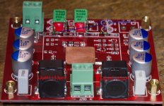
The coils on my 2.1 boards are marked 150 and get about 29 degrees C. also the same as their (bigger) heatsink.
None have active cooling and the ambient temp. is 18C.
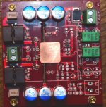
My older modules have a 3300uF Rubycon cap, the newer one has a 3300uF Nichicon. Just like yours, but the capacitors next to the coils are all grey (684j63) on my boards, not yellow (105j100). All the coils on my boards have a clear marking: "100" with a blue circle around them.
I have no oscilloscope to check the frequency.
Last edited:
Sorry for recommending them; top of the coils of my modules get about 42 degrees Celcius, same as the heatsink when I put 19V on them for a couple of hours. Is that to hot?
The coils on my 2.1 boards are marked 150 and get about 29 degrees C. also the same as their (bigger) heatsink.
None have active cooling and the ambient temp. is 18C.
My older modules have a 3300uF Rubycon cap, the newer one has a 3300uF Nichicon. Just like yours, but the capacitors next to the coils are all grey (684j63) on my boards, not yellow (105j100). All the coils on my boards have a clear marking: "100" with a blue circle around them.
I have no oscilloscope to check the frequency.
Groetjes,
42 degrees Celsius hints a problem with a too low switching (carrier) frequency. With a multimeter (without amplifier power), measure the value (approximately) of R2 and R3. If R2 has a value less than R3, the TPA3116 is most likely set up as a "slave" and the frequency is too low. In such case, I suggest you to swap the two resistors around and cut pin 16.
- Home
- Amplifiers
- Class D
- TPA3116 D2 mono amplifier as a stereo system?