Got it! Thank you againHi,
Doc is 2,9M size, it can't be posted on DIYA. If interrested PM me, I'll initiate a WeTransfer.
Please note that the doc is in french.
Rgds
")
First of all, Happy New Year !
I wish all of you and your families health and prosperity. A lot of wonderfull projects and sharing !
On my side, I hope that 2019 will bring a successfull TAS3251 project
Thanks for the proposal. My problem with the LM5010 is the thermal pad below. I will solder SMD for the first time, and want to improve my chances of success. We had a discussion previously about avoiding that thermal pad, and you had proposed the MP2459, pin to pin compatible with the LMR1606 ([design log] Neat 2x170W I2S in, I2C controlled, integrated DSP amp (TAS3251))
LM5007 also seems to do the job.
What are the benefits of the LM5010 over the MP2459, LMR1606 or LM5007 ?
From the TI webench design file, I see a switching freq of 2.1 MHz in my design. You speak of 500 kHz. What is to be looked after ? What is the best for our applications : higher or lower ?
Things have to be as simple as possible, but not too simple. Is there a drawback at going directly to 12V with the first regulator and skipping the LM2940 ?
As there are no comments yet, I understand that the TLV1117 connected to the 12V is OK for 3.3V (and that associated caps make sense).
Best regards,
JMF
Help Doctomord
I would really appreciate having a bit more explanations about your comment. I would like to design a not too bad power part as it is really important for the overall performance.
Best regards,
JMF
As I said, higher frequencies ratio means less chance for a beat-tones. Second, my IC needs less inductance, that's critical in my case due to >300mA load(no start-stop mode). The coil I used is TDK 1210 sized. 2MHz ripple very easy to suppress with 10u X7R, with 400kHz I probably need 5x more caps to get the same clean rail, I have no room for that.
Well, 300mA minimum load current (in your case) is something everyone interested in this discussion needs to know to interpret the results and circuit parameters. Regarding beat-tones, it is possible even with 2MHz when the amp runs at 500kHz for example. Even 900MHz transceiver can get you beat-tones if your preamp isn't emi-hardened due to demodulation products on the inputs.
doctormord, I really have no idea what you talking about, and actually not the first time. I remember you tried to protect initially failed idea to keep SMPS apart from an amp, now seems you don't believe another obvious thing. Maybe I did something to insult you or did provoke your emotional crisis? Forgive me please, my friend, it wasn't intentional(I'm reading that forum ok if 1 time/week, I can miss any question to me easily etc), and further, please, let's keep the discussion in tech aspects. I personally, try to operate in the following mode: if I see any chance to make things better, even only in theory without practical confirmation, I do. In case of 2MHz buck, I got a few advantages described above. I do thing much less reasonable than 2MHz buck, for instance, I migrate from cheap LDO to low-noise one(13uV 100-100kHz) without any measurable advantages + additional BOM cost. The same situation around a rail aluminum caps which I add more and more even if it does not affect the result anymore. I'm pretty much a maniac or let's say true-DIYer if we talking about product improvement
I can't see where this discussion went out of technical focus. No worries mate, I haven't or had an emotional crisis.
This is your design goal, not mine. As my projects are mostly all battery powered or "mobile use" there is no need to have a supply directly bundled to the amp. To my knowledge, that's what I said. Lastly remember the language barrier, I'm not a native english speaker, same as you.
I remember you tried to protect initially failed idea to keep SMPS apart from an amp,
This is your design goal, not mine. As my projects are mostly all battery powered or "mobile use" there is no need to have a supply directly bundled to the amp. To my knowledge, that's what I said.
Lastly remember the language barrier, I'm not a native english speaker, same as you.Help Doctomord
I would really appreciate having a bit more explanations about your comment.
JMF
I'd prefer the LM5010 due to the fact it is an COT (constant-on-time) converter. Among other things this means, it wont switch unpredictable at light loads and, important to me, is easy to use as a flybuck converter to generate a second output voltage, either isolated or ground referenced with independed polarity. So generating i.e. clean symmetrical +/-12V for an analog frontend is possible with ease.
Normally nothing wrong with the others like the MP2459 or LMR16006 but take note, the MP24XX need external pullup-resistor to enable, while the LMR16 have an internal pull-up current source and can be left floating to enable. (When MP24XX EN pin is left floating, the IC is disabled)
Make sure to avoid LMR16XX ECO mode is it implies some kind of frequency shift additional to the pulse-skipping behaviour. The MP24XX does pure pulse-skipping at light loads (afaik).
.. Second, my IC needs less inductance, that's critical in my case due to >300mA load(no start-stop mode). The coil I used is TDK 1210 sized. 2MHz ripple very easy to suppress with 10u X7R, with 400kHz I probably need 5x more caps to get the same clean rail, I have no room for that.
Would you mind telling us the exact inductor used here? Assuming Vin=24V, Vout=3.3V, Iout=0.3A with 30% dILpp ripple, about 15uH is needed at 2MHz. I haven't found a TDK 1210 inductor which is able to handle this with good efficiency so far.
Last edited:
Thanks to both of you for the advices about the poweer supply of my project.
So I understand that, as a basic rule of thumb, the higher the swithching frequency, the better. Provided that the PCB layout is not wrong.
Another issue is with light loads when the " intelligent" device may adjust its frequency. Hence the interest in our applications of Constant on Time devices.
I understand last that the different solutions are still acceptable for my target of "good design" without looking for perfect/ultimate design. So I will go to something easy to solder.
Last , I'm not clear if there are drawbacks to go directly to 12V with the MP2459 or LMR16006 and skipping the LM2940 (compared to the EVM design that goes to 15V and then use a MP2940 to build the 12V)?
Best regards,
JM
So I understand that, as a basic rule of thumb, the higher the swithching frequency, the better. Provided that the PCB layout is not wrong.
Not in general, it depends on voltage differential, load current and efficiency goal.
The point here is to push the switching frequency of the voltage converter away from the switching frequency (and their harmonics) of the amplifier to avoid "beat-tones" which may occur as a subharmonic oscillation product between these two frequencies.
I.e. When amp is running at 600kHz and your SMPS is at 605kHz, beat-tones at 5kHz (and their harmonics) may occur. As frequency of both always shifts a bit due to temperature and load current, it's not only a single tone but something like a "weeping noise". This is an example but effects are not limited to just that.
Another issue is with light loads when the " intelligent" device may adjust its frequency. Hence the interest in our applications of Constant on Time devices.
Right, avoid frequency foldback and burst-mode. COT is prefered/needed if flybuck is going to be used to generate a second output voltage. The other controllers are fine if "possible issues" keeped in mind and the converter is calculated/layed out right.
Last , I'm not clear if there are drawbacks to go directly to 12V with the MP2459 or LMR16006 and skipping the LM2940 (compared to the EVM design that goes to 15V and then use a MP2940 to build the 12V)?
When using a relatively high converter switchinh frequency, the following LDO can be ommited as their is most likely no benefit on filtering. (Just have a look into the datasheet of the LDO to see their PSRR/CMRR at switching frequency. Pretty much all don't do much at frequencies above 100-200kHz) Filtering with simple RC or LC filter is more effective.
The EVM converter is running at rougly 66kHz. (Calculated from LM5010 datasheet equation 7, page 11 with known Ron=182kOhm from TAS3251EVM schematic)
LM5010: http://www.ti.com/lit/ds/symlink/lm5010a.pdf
TAS3251EVM:http://www.ti.com/lit/ug/slau757b/slau757b.pdf
I'd recommend getting one of the "cheap" reflow stations for those kinds of ICs, makes repair easier as well.
If you're on a budget, get a 858D:
Neu SMD Heißluftlötstation Digital Rework Station Lötstation + 3 Nozzles 858D | eBay
If you want an "okay" soldering iron combined into this, get a 898D:
SMD 898D+ Digital Rework Station Heißluftlötstation Heißluft Entlötkolben W.E.P | eBay
I have the latter, they are okay for the money and handy for repairs and all kind of heat shrinking. The soldering iron is at about 40W, with simple bang-bang-control. Not to bad. Basically it's the same as the older 938 Aoyue types of soldering iron skillet. I use two 938 since about 15years now.
Just make sure their earth-connection is working and low resistance.
Last edited:
I'd recommend getting one of the "cheap" reflow stations for those kinds of ICs, makes repair easier as well.
If you're on a budget, get a 858D:
Neu SMD Heißluftlötstation Digital Rework Station Lötstation + 3 Nozzles 858D | eBay
If you want an "okay" soldering iron combined into this, get a 898D:
SMD 898D+ Digital Rework Station Heißluftlötstation Heißluft Entlötkolben W.E.P | eBay
I have the latter, they are okay for the money and handy for repairs and all kind of heat shrinking. The soldering iron is at about 40W, with simple bang-bang-control. Not to bad. Basically it's the same as the older 938 Aoyue types of soldering iron skillet. I use two 938 since about 15years now.
Just make sure their earth-connection is working and low resistance.
Thanks for the links. We have such things at the Fablab. But is is not clear to me how to use those to solder the LM5010 bottom pad. I'm sorry for this basic question that shows my ignorance. But I'm willing to learn.
Is it something like this YouTube
Or something like YouTube ?
Are you using solder paste / stencil ?
JMF
Last edited:
I see that some of the designs developped here have commercial intentions. I don't have. Moreover, due to my lack of knowledge in some areas, I need collaboration to succeed having something working. But I don't see a lot of open designs here (gerbers at the most)
Question: do you think that going "fully open source" and sharing KiCAD source files would help ?
Is there a risk that experienced contributors may step back fearing to see their advices and contributions injected in easily accessible files ?
I don't think that what I do is rocket science, but I would like to go in a direction that maximizes contributions.
JMF
I would certainly contribute. The problems I see:
-How to make a final design decision in a group of contributers?
-How to work in a shared folder with the possibility of multiple people editing the same file? Or how would people contribute?
-Who is taking the risk for final production?
-How to make a final design decision in a group of contributers?
-How to work in a shared folder with the possibility of multiple people editing the same file? Or how would people contribute?
-Who is taking the risk for final production?
JMF, it's like shown in the videos, that way you may solder the LM5010.
For the point about sharing your project files, another option is, that you see your efforts done all the way finally in a product from China. Been there, done that.
Btw. people with commercial interest mostly give the least contribution in detail at design phase. (personal experience)
For the point about sharing your project files, another option is, that you see your efforts done all the way finally in a product from China. Been there, done that.
Btw. people with commercial interest mostly give the least contribution in detail at design phase. (personal experience)
I would certainly contribute. The problems I see:
-How to make a final design decision in a group of contributers?
-How to work in a shared folder with the possibility of multiple people editing the same file? Or how would people contribute?
-Who is taking the risk for final production?
My idea was more basic. Like the TI EVM that people can have details about and start from, build upon.
It seems to me that we may all have different constraints, habits, understandings... So converging to a unique design that suits all has high probabilities to fail.
So it was more about allowing project "forks" based on shared work.
JMF
JMF, it's like shown in the videos, that way you may solder the LM5010.
For the point about sharing your project files, another option is, that you see your efforts done all the way finally in a product from China. Been there, done that.
Btw. people with commercial interest mostly give the least contribution in detail at design phase. (personal experience)
Yes, I understand this. As I don't have commercial interest for this project, my preferred option would be for it to be open to the community. Even OK for me for Chinese cloning if it derives in good product that I can buy for cheaper than I can make it by hand.
But it is important that going open won't prevent people like all those providing advices here, to contribute. This is my fear.
An alternative would be to PM files between interested contributors (or having a restricted access folder). And only publish PDF on the forum.
Don't know what is the best,
JMF
Hello,
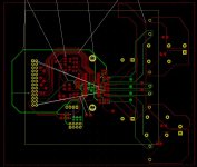
The project is not completely stalled. I decided to start routing the project, event if it was not completly finalized. Sort of curiosity bias... Lot of professional activities aside made progressing slow.
For the routing, I took some inspiration from the TAS3251EVM (unfortunatly 4 layers) and from the TPA3255EVM (2 layers).
For hand soldering, I went to 0805 everywhere, replacing the 0402 and 0603 by bigger ones.
I still have to route the powersupply modules.
This is my first PCB of all my life... So I would really need advice about:
- the PCB, and avoiding the mysterious "ground loops",
- avoiding PCB mistakes
- tuning the values and part number of some caps and the coils.
10cmx10cm seems quite dense for the design. This was my target because of the super low PCB manufacturing prices, but 15x15 would be more reasonable.
However it moves forward ! I arrive to something like the schema below.
Other interesting news: they published more detailed information on the chip programming on TI site. I think that we have now the registry adresses.
The project is not completely stalled
. I decided to start routing the project, event if it was not completly finalized. Sort of curiosity bias... Lot of professional activities aside made progressing slow.For the routing, I took some inspiration from the TAS3251EVM (unfortunatly 4 layers) and from the TPA3255EVM (2 layers).
For hand soldering, I went to 0805 everywhere, replacing the 0402 and 0603 by bigger ones.
I still have to route the powersupply modules.
This is my first PCB of all my life... So I would really need advice about:
- the PCB, and avoiding the mysterious "ground loops",
- avoiding PCB mistakes
- tuning the values and part number of some caps and the coils.
10cmx10cm seems quite dense for the design. This was my target because of the super low PCB manufacturing prices, but 15x15 would be more reasonable.
However it moves forward ! I arrive to something like the schema below.
Other interesting news: they published more detailed information on the chip programming on TI site. I think that we have now the registry adresses.
Attachments
- Home
- Amplifiers
- Class D
- [design log] Neat 2x170W I2S in, I2C controlled, integrated DSP amp (TAS3251)