So, what's up...
Discussions on power supplies help to define the direction on that topic.
I also studied a bit the PPC3 cnfiguration software. Thisis a nice piece of software. All filters I need are represented. It is possible to directly fill the biquad values.
There are possible delays between the tweeter and the woofer.
One not so nice thing is the structure of the fixed worflow:
15 Biquad common to both channels, but only 5 dedicated to the Woofer and 5 to the Tweeter. And the gain level adjustment, if needed in one of those 5 biquads.
This is less than perfect for implementing LXmini, where the tweeter needs 6 biquad + gain => 7 for 5 offered.
A work around is to use the 15 common biquads, for frequencies far above the corossover frequencies, where the impact on the woofer will be negligeable. This is not a shostopper... but... not perfect.
I'm learning about KiCAD now. It took some time to admit that the import from Altium was not good enough to provide a robust basis for the project. It appears that it will be better to start from scratch, getting the inspiration from the TI design.
JMF
Hi, I'm not sure about the interpretation of your tests. It seems that the 150W, even with capacitor banks is not doing the job. But what is the result with the 350W one ?
Best regards,
JMF
hi jmf
i am a noob....i just want to see on scope
")
i want to check the statements by the experts vs my old mind thinking of the transformer and caps + crc in my head.
my conclusion is.
if the smps i good designed for about 150W and the 6,5A ( small tolerance to get little more power..about 175W) ..look at
YouTube
so you cannot get more power eg. less than 4 ohms (i try 2,6ohms) because the currrent is not possible= hickup mode will start...with or without caps!!
read the other thread of ivx...
regards
chris
And the gain level adjustment, if needed in one of those 5 biquads.
If absolutely needed, it can also be done with the volume control registers (0.5dB precision). This is less than optimal of course, but it is possible
In PPC2 it was the case that higher than 2th order filters have to be constructed (cascaded) with lower order filters. If that is still the case, you run out of biquads pretty fast when you use higher order filters.
By the way, I just identified that PS reference design from TI, that would perfectly fit the TAS3251: PMP10215 Universal Input to 3.3V, 12V, 36V, 200W Continuous PSU for Class-D Amplifier Reference Design | TI.com
- 36V and delivers 200W continuously and 840W peak
Low cost PFC + 2-switch forward topology provides 200W average, 840W peak power
Constant switching frequency: particularly suitable for audio applications
Simple thermal inteface: two small heat-sinks placed on one side of the board
Good plug-to-plug efficiency: 84% @ 115Vac, 86% @ 230Vac
Compact construction: 126mm x 145mm, height 35mm
Maybe that transfos/inductors can be bought by Wurth: Transformers and Inductors for Texas Instruments 200W Audio Power Module
A simplified version would be perfect
Advices about inductors here: TPA3255 - all about DIY, Discussion, Design etc.
In PPC2 it was the case that higher than 2th order filters have to be constructed (cascaded) with lower order filters. If that is still the case, you run out of biquads pretty fast when you use higher order filters.
Same in PPC3,
JMF
Hummm, I face a dilemna....
I like tyhe simplicity of the TAS3251 BOM and the integrated concept. However, as the chip is a DAC/DSP combined with the Amp on the same silicon, but with "external" interconnection, I wanted to keep the possibility to include a "distortion device" between both. More on that at the bottom.
Today, I discovered this (posted by Nelson Pass): B1 with Korg Triode. Exactly what I could look for.
But how to include that between a balanced out DAC and a blalanced in amp ?
Going from balanced to SE, inserting the Korg the triode, and then back to balanced would completly break the balanced spirit of the chip...
Could it be more simple than I would think ?
Why: basically because my STA326 FX-Audio D802 has a lot of looked after qualities: transparency, image, dynamics.... But I have no better word than saying that I always had a mixed feeling of something not emotionally engaging. Maybe too "clinical".
I would be interested in experimenting the addition of triode like distortion. Either by something like above, or through DSP. It seems that DSP triode filter is not easy, and at least not open source (didn't find it at least).
So at the end a modern triode buffer looked appealing to have some experiments. But I don't know how to have that possibility fit in my design.
JMF
Humm project stalled for 2 weeks...
I may have been bitten by some sort of Nelson Pass designs bug. It may be related to so good memories from one of my previous systems with Supravox OB, and a 1W class A super simple amp.
Also by some drawbacks of the DSP part of TAS3251 (not show stpper but annoying), and the policy of TI for their configuration tools which does not seems so open.
So I still like the idea, but I recognize that it may lacks some flexibility.
Exemple: difficult to use with B11 Korg triode preamp "in the loop".
Balanced connection between DAC and Amp has also pro and cons as of flexibility perspective.
Will still work on learning KiCAD on this basis.
JMF
... Have to think twice about it
Also by some drawbacks of the DSP part of TAS3251 (not show stpper but annoying), and the policy of TI for their configuration tools which does not seems so open.
Professional opinion
Hello,
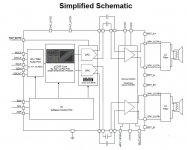
I resumed the project. I worked a bit on it during holidays to start implement the basic schematics and design choices in the EDA. I have choosen KiCAD as it is a open source software, and this project intends to be open itself.
I will publish the files along.
I basically started from the TAS3251EVM, and simplified progressivly the board to:
- suppress the post filter feedback,
- just keep the I2S, I2C and I/O to control the amp from a microcontroller or Raspeberry PI
- simplified the power supply section as I need less power values and look for easy hand soldering.
Below the first draft.
Power cascade is 36V => LMR16006Y (designed with TI tools) => 15V => LM2940 => 12V => TLV1117-3.3 => 3.3V.
I do may best, by as my background is quite far, I more rely on integration of blocks I have found than accurate knowledge.
Feedback to correct errors or improve the design would be much appreciated
And happy new year !!!!
JMF
Attachments
Hello,
I resumed the project. I worked a bit on it during holidays to start implement the basic schematics and design choices in the EDA. I have choosen KiCAD as it is a open source software, and this project intends to be open itself.
I will publish the files along.
I basically started from the TAS3251EVM, and simplified progressivly the board to:
- suppress the post filter feedback,
- just keep the I2S, I2C and I/O to control the amp from a microcontroller or Raspeberry PI
- simplified the power supply section as I need less power values and look for easy hand soldering.
Below the first draft.
Power cascade is 36V => LMR16006Y (designed with TI tools) => 15V => LM2940 => 12V => TLV1117-3.3 => 3.3V.
I do may best, by as my background is quite far, I more rely on integration of blocks I have found than accurate knowledge.
Feedback to correct errors or improve the design would be much appreciated
And happy new year !!!!
JMF
D3 should be Schottky, not Zener
what is J10 ?,
what's expected current through this boost regulator ? , C49+C50 are small caps, but may be enough is there's only a low current.
D3 should be Schottky, not Zener
what is J10 ?,
what's expected current through this boost regulator ? , C49+C50 are small caps, but may be enough is there's only a low current.
J10 is derived from the TAS3251EVM board. It is a "PCB Shorting Link, Fixed Jumper Link" https://www.harwin.com/products/S1911-46R/
I may suppress it.
The 15V boost regulator has to fit for: 90mA for GVDD and VDD @12V + the supply of the DSP and the DAC at 3.3V which seems to be minimal. So let's say 100 mA.
I attach the design file from TI for that stage.
I will correct the Diode type, you are right.
And I have to thank you agian for the link to the tutorial on PCB design from David L. Jones, which is really well done, and just near me on my desk.
JMF
Attachments
Why are you taking out the DAC-output? What is it for?
//
I, not sure what your question is. I'll make an attempt to answer. Let me know if it provides the expected answer or please clarify the question.
The TAS3251 is a DSP+DAC +TPA3251 on the same silicium. The wires from the DAC go out of the chip on some pin, and have to be connected to the amp part of the chip via some other pins: its is an external connection. So you see the DAC outputs connected to the amp inputs.
Attachments
First of all, Happy New Year !
I wish all of you and your families health and prosperity. A lot of wonderfull projects and sharing !
On my side, I hope that 2019 will bring a successfull TAS3251 project
Thanks for the proposal. My problem with the LM5010 is the thermal pad below. I will solder SMD for the first time, and want to improve my chances of success. We had a discussion previously about avoiding that thermal pad, and you had proposed the MP2459, pin to pin compatible with the LMR1606 ([design log] Neat 2x170W I2S in, I2C controlled, integrated DSP amp (TAS3251))
LM5007 also seems to do the job.
What are the benefits of the LM5010 over the MP2459, LMR1606 or LM5007 ?
From the TI webench design file, I see a switching freq of 2.1 MHz in my design. You speak of 500 kHz. What is to be looked after ? What is the best for our applications : higher or lower ?
Things have to be as simple as possible, but not too simple. Is there a drawback at going directly to 12V with the first regulator and skipping the LM2940 ?
As there are no comments yet, I understand that the TLV1117 connected to the 12V is OK for 3.3V (and that associated caps make sense).
Best regards,
JMF
I wish all of you and your families health and prosperity. A lot of wonderfull projects and sharing !
On my side, I hope that 2019 will bring a successfull TAS3251 project
I'd go for the LM5010 in change for the LMR16xx and skip the post regulator. Just step down to 12ish volt running at about 500kHz or more. For the 3.3V you can just use an LDO then if needed.
Thanks for the proposal. My problem with the LM5010 is the thermal pad below. I will solder SMD for the first time, and want to improve my chances of success. We had a discussion previously about avoiding that thermal pad, and you had proposed the MP2459, pin to pin compatible with the LMR1606 ([design log] Neat 2x170W I2S in, I2C controlled, integrated DSP amp (TAS3251))
LM5007 also seems to do the job.
What are the benefits of the LM5010 over the MP2459, LMR1606 or LM5007 ?
From the TI webench design file, I see a switching freq of 2.1 MHz in my design. You speak of 500 kHz. What is to be looked after ? What is the best for our applications : higher or lower ?
Things have to be as simple as possible, but not too simple. Is there a drawback at going directly to 12V with the first regulator and skipping the LM2940 ?
As there are no comments yet, I understand that the TLV1117 connected to the 12V is OK for 3.3V (and that associated caps make sense).
Best regards,
JMF
@ AIM65
This link from your post #19 is dead. Could you please post an actual link, or upload the file here or PM me this document?
This link from your post #19 is dead. Could you please post an actual link, or upload the file here or PM me this document?
Link to First doc : https://www.robertponge.com/telechargements/ebooks/kicad-2.pdf
- Home
- Amplifiers
- Class D
- [design log] Neat 2x170W I2S in, I2C controlled, integrated DSP amp (TAS3251)