I am sorry to learn about another fireworks. This time you had made a nice mechanical construction and you diligently checked the power supply before turn-on. You deserve some success.
Power supply polarity on the board: As far as I can see from the photo of the amplifier, it includes a polarity protection diode. Even a wrong polarity should not damage the board.
As it has been said by other, your power supply has insufficient current capacity to run two boards. It does not mean, this insufficient current rating should be the reason for the second fireworks. You only turned on one amplifier and did not load the amplifier.
As I understand, you had no loads on the amplifiers when turning the first one on. The amplifier you show is a class D amplifier and you should NEVER turn a class D amplifier on without a reasonable load.
Follow this link and read the two postings by "ddapkus" from TI: TPA3116D2 Amp
The output of a class D amplifier is an LC resonant filter and that filter can do a lot of damage without damping from the load.
The filter (inductance) may have damaged the TPA3116 output stage such that it shorted and the power supply was then overloaded. A possibility.
You discuss with another forum member about grounding of speaker terminals. That worries me a little. The "old" class AB amplifiers with a symmetrical power supply or a large capacitor in series with the output, operated with one speaker terminal to ground. Most modern IC amplifiers use a bridged output with two amplifier outputs operating in counter-phase. If you have introduced a grounding somewhere, that is an obvious reason for troubles.
You could smell overheating (and see smoke?). Any idea if it was the amplifier or power supply?
You have one amplifier left. Are you sure if it is unharmed or did it take part in the first fireworks?
When I have to test a new amplifier, I first try to test it with a moderate voltage where it should still work. Less voltage and current - less energy to fry the amplifier in case of fault. The board you show should be able to run all the way down to 6V. Would you have a 9V or 12V DC power supply (1A or more) just to test if the last amplifier is OK or not?
Check if your power supply is still alive after the second accident. Check without load.
If the power supply is OK and the amplifier is OK as well (tested with a lower voltage), I suggest you remove the amplifier from the chassis for a moment and do the basic connections (speakers, power supply and source) directly on the board terminals so the connections are easy to check. Only when you know the parts can work together, you do a corresponding implementation in the chassis.
Fingers crossed and good luck!
Last edited:
Thank you again Faux French, that is first rate information, and clearly written too.
The link to the PSU is wrong sorry. It is a 24v 6 amp "Minger" (Great Name).
Alas all four boards are now toast, and the last board died in a most vexing manner. . . .
I had connected to up direct to speakers, and direct to power supply. It actually worked! The sound was quite good, playing through some large 8ohm speakers.
But when later I tried it out again, still in the same configuration the PSU kept switching itself on and off in a cycle, and the amplifier making a phut . . .phut. . .phut noise.
I tried a differnet PSU . . same thing.
I tried the 24v PSU on an LED lamp, it works OK. . .. .
I have given up and will buy a ready made amp. Probabaly a Yamaha AS201, I would welcome suggestions for amp purchase (min 200W).
Thank you all for you help, I am abandoning this project it is too depressing.
If any one would like the broken boards for parts then I will list on ebay to cover postage. Probably large first class per board?
Thank you again Faux French, that is first rate information, and clearly written too.
The link to the PSU is wrong sorry. It is a 24v 6 amp "Minger" (Great Name).
Alas all four boards are now toast, and the last board died in a most vexing manner. . . .
I had connected to up direct to speakers, and direct to power supply. It actually worked! The sound was quite good, playing through some large 8ohm speakers.
But when later I tried it out again, still in the same configuration the PSU kept switching itself on and off in a cycle, and the amplifier making a phut . . .phut. . .phut noise.
I tried a differnet PSU . . same thing.
I tried the 24v PSU on an LED lamp, it works OK. . .. .
I have given up and will buy a ready made amp. Probabaly a Yamaha AS201, I would welcome suggestions for amp purchase (min 200W).
Thank you all for you help, I am abandoning this project it is too depressing.
If any one would like the broken boards for parts then I will list on ebay to cover postage. Probably large first class per board?
My condolences with the boards. A sad start to DIY. I will send you a "PM" (private message).
I had no idea you shouldn't run a class D without speakers. I have done it countless times, with this very chip.
Are there any instances of failure, or is this just theory or outdated?
On topic, go to the speaker out spring clips, and check for continuity between the negatives. Using the circuit board that came with the box could mean the grounds are tied together.
Are there any instances of failure, or is this just theory or outdated?
On topic, go to the speaker out spring clips, and check for continuity between the negatives. Using the circuit board that came with the box could mean the grounds are tied together.
I had no idea you shouldn't run a class D without speakers. I have done it countless times, with this very chip.
Are there any instances of failure, or is this just theory or outdated?
On topic, go to the speaker out spring clips, and check for continuity between the negatives. Using the circuit board that came with the box could mean the grounds are tied together.
Yesterday, I made a posting on this thread mentioning our forum member "ddapkus". He is/was audio application manager at TI. In a thread concerning TPA3116 (see link in my posting), he actually deals with a case of a destroyed output filter capacitor and explains how to prevent such. ddapkus has made 2nd and 3rd postings in that thread.
Personally, I have destroyed a TDA8954 chip due to a moment without loading and a flawed implementation of the snubber circuit.
The problem is the inductor in the filter. Without load, the LC filter (normally used well above the resonance frequency) may be triggered at the resonance frequency and generate quite high voltages. Then, the output filter capacitor(s) is in danger. The inductor may also "kick back" to the amplifier chip output and generate some unpleasant voltage spikes. Then, the class D IC is endangered.
ddapkus explains how to include catch diodes to protect the IC output (3rd posting). Further, catch diodes at the filter output will save the output capacitor. It just becomes a lot of protection diodes.
Last edited:
Thank you Faux French. I did look at your link but 1000+ pages made my head hurt before I started. Sorry you had to repeat yourself.
I will be a bit more cautious with the one's I have modified. Especially where I create a path on the speaker side of the choke. Which have the greater influence over the chokes use when no speaker is connected.
I don't build chip amps from scratch, but I certainly see how this effects me when I doctor one. I was puzzled before as no commercial class D's I have seen carry warnings. That's not what we are talking about in this instance though. The OP is though. So I doubt leaving his amp open ended was his issue. Though it is baffling if his speaker grounds are not tied to the case. It makes me want to see it in person, but he's not local to me (Nottingham)
Fault investigation on TPA3116 boards.
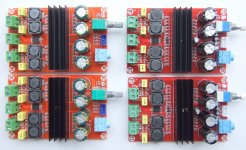
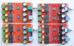
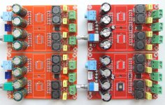
I was very happy to pick up four defect TPA3116 boards. New challenges ahead.
I will briefly describe my findings and a method to use when looking for unknown defects in electronic amplifier boards. Many on this forum are far more experienced in repair than I, but some young DIYs may benefit from improved systematics.
VISUAL INSPECTION.
The most obvious, but often neglected part of electronic fault finding is giving the board a thorough look for mechanical abnormalities. Overheating, poor connection, wrong polarization, wrong connection, wrong mounting etc. are quickest noticed by looking carefully at the board.
On top, you may spot important details of the board.
For the four boards, the first impression was very good. No obvious defects were spotted with the heatsinks in place. The components on the boards were generally selected well according to the standards for such rather cheap boards.
Only the choice of the output filter chokes was awkward. TI recommends 10uH (with 680nF). On the board 33uH was used. Standard 12x12x7mm enclosed chokes. That the cut-off frequency is chosen lower is not a main concern, but the current rating is. The higher the inductance (using the same core), the less is the maximum current before saturation. Such 12x12x7mm cores with 33uH can handle around 3A (peak) before saturation. That corresponds to some 2Arms. 2Arms may just do for 8 Ohm loads but not for 4 Ohm and even less for 2 Ohm. Had the same cores been used for 10uH (as recommended), the current rating would have been considerably higher and 4 Ohm speakers could have been used at full output power without saturation. More bizarre, two TPA3116 chips are used on a board for PBTL coupling to allow low impedance loads (below 4 Ohm). But, the filter chokes will saturate with such low impedance loads. Something vent wrong in this part of the design.
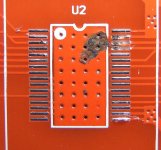
When the heatsinks were removed, two similar defects were spotted on two of the four boards. For two of the in total 8 TPA3116 chips, a few pins had suffered current overload damages. In particular the pins on one of the chips. The pins and corresponding PCB pads had disappeared. Such damage hinted faults on at least these two chips.
It was clear that at least the board with the most substantial damage could not be repaired. The chip housing is very small (TSSOP) and the PCB tracks equally narrow. As important parts of the output track was gone, no repair was worth the effort.
TEST WITH AN OHM-METER.
A very simple but surprisingly efficient method is the use of an Ohm-meter. A large share of faults in else functional amplifier designs can be detected on the output terminals or the power supply terminals. Very often an output “hangs” on (shorted to) either ground or supply level. Or, the supply line is simply short-circuited.
For the test, I use the 20 KOhm range or 2 KOhm range and no power or connections to the amplifier board.
For a start, I test the power supply terminals with the 20 KOhm range. The red measuring probe on the “+” terminal for the power supply. If the board has a polarity protection diode, such as these four boards, the red probe has to be moved to the cathode of the protection diode. The black measuring probe on the “-” terminal for the power supply. If the power input of the amplifier is in good shape, the resistance value seen on the Ohm-meter will slowly and regularly increase as the Ohm-meter test voltage charges the on-board decoupling capacitors. If the resistance remains steady and low, the power supply line is likely to have a short-circuit somewhere. For amplifier boards with symmetrical supply, the test has to be carried out for both rails.
All four TPA3116 boards had a short-circuit towards ground (measured after the polarity protection diode).
If the power supply input is fine, then on to the speaker outputs. With one of the measuring probes on the power supply “-” terminal and the other measuring probe connected sequentially to the speaker output terminals. If any of the speaker output terminals have an impedance below 100 Ohm toward the supply “-” terminal, there is reason to worry. If all is still fine, the same test is conducted from the power supply “+” terminal and toward the speaker output terminals (sequentially), still looking for less than 100 Ohm impedance. When a symmetrical power supply is used, also the negative rail has to be tested toward the speaker output terminals.
The four TPA3116 boards all showed at least one speaker output terminal to hang on the “-” (ground) terminal. None of the outputs hang on the “+” terminal. Only one TPA3116 chip had outputs not hanging on either the “-” or “+” supply lines.
For the four boards tested here, all had an apparent short-circuit from power “+” to ground (“-”). And, all chips but one had at least one output hanging on power supply ground. The low impedance to ground could be caused by a short-circuit to ground in the output filters, but then the short-circuits between power supply “+” and power supply “-” would not fit in.
As two TPA3116 chips anyway had to be removed from the boards because of pins damage, they were removed such that these output filters were isolated and could be tested without influence from the chips. Both these two output filters were fine and the lines “floating”. Then, all the other TPA3116 chips were removed, except for the chip with no outputs hanging. All output filters seemed to be fine. Also, then all tests of the power supply lines were successful.
The board with only one (perhaps good) chip was tested with 10V/300mA, speaker and source. That channel worked flawlessly, even with 25V of supply.
Post mortem analysis is uncertain. The output stages of almost all TPA3116 chips had been ruined on the low-side. One output lines had suffered serious damage due to excessive current. The chip outputs were without doubt involved in the initial havoc. Either from output short-circuit/wrong connection, or from a high voltage “kick-back” of the filter chokes (no catch-diodes to protect chip outputs) eventually due to missing load. The destruction of the low-side switches/drivers resulted in short circuit of the power supply lines.
REPAIR.
New TPA3116 chips have been ordered and are on their way. They come from far away and it will take a while. As all boards now measure as boards that normally work, I guess the new TPA3116 chips will solve the malfunctions.
Soldering of the very small TSSOP housings will be done following the method disclosed on YouTube and taking advantage of the surface tension of melted solder. Lots of solder on the small leads and subsequent removal of the excessive solder as drops.
GENERAL OBSERVATIONS.
The boards are advertised as 2x100W. Impressive for that size and price. Credible? - only with restrictions. The TPA3116/18 are limited in output power by their maximum supply voltage of 26V. A supply voltage of 26V leaves the voltage “clipping point” at 2x35W (8 Ohm) and 2x70W (4 Ohm). No 2x100W.
But, these boards use PBTL coupling with one TPA3116 chip per channel. The TPA3116 chip is conceived as BTL so the output power cannot be raised by increasing the voltage on the load. PBTL only helps increasing the current that can be handled. According to the datasheet, the TPA3116 can handle the current in a 4 Ohm load with maximum supply voltage using ordinary BTL. Why then PBTL? PBTL leaves half the switch impedance (impressive 60mOhm) and perhaps double the current rating. Looking at the TSSOP (Terribly Small ) housing and leads, I am not fully assured. But, in theory the PBTL coupled TPA3116 can handle loads with impedances below 4 Ohm. Such low impedance speakers may be found in vehicles. Normal cars have 12V systems so 2x100W is not possible here (only far less). But, for a truck with 24V electrical system it may be possible.
In short, never rely much on such surprising specifications.
I was very happy to pick up four defect TPA3116 boards. New challenges ahead.
I will briefly describe my findings and a method to use when looking for unknown defects in electronic amplifier boards. Many on this forum are far more experienced in repair than I, but some young DIYs may benefit from improved systematics.
VISUAL INSPECTION.
The most obvious, but often neglected part of electronic fault finding is giving the board a thorough look for mechanical abnormalities. Overheating, poor connection, wrong polarization, wrong connection, wrong mounting etc. are quickest noticed by looking carefully at the board.
On top, you may spot important details of the board.
For the four boards, the first impression was very good. No obvious defects were spotted with the heatsinks in place. The components on the boards were generally selected well according to the standards for such rather cheap boards.
Only the choice of the output filter chokes was awkward. TI recommends 10uH (with 680nF). On the board 33uH was used. Standard 12x12x7mm enclosed chokes. That the cut-off frequency is chosen lower is not a main concern, but the current rating is. The higher the inductance (using the same core), the less is the maximum current before saturation. Such 12x12x7mm cores with 33uH can handle around 3A (peak) before saturation. That corresponds to some 2Arms. 2Arms may just do for 8 Ohm loads but not for 4 Ohm and even less for 2 Ohm. Had the same cores been used for 10uH (as recommended), the current rating would have been considerably higher and 4 Ohm speakers could have been used at full output power without saturation. More bizarre, two TPA3116 chips are used on a board for PBTL coupling to allow low impedance loads (below 4 Ohm). But, the filter chokes will saturate with such low impedance loads. Something vent wrong in this part of the design.
When the heatsinks were removed, two similar defects were spotted on two of the four boards. For two of the in total 8 TPA3116 chips, a few pins had suffered current overload damages. In particular the pins on one of the chips. The pins and corresponding PCB pads had disappeared. Such damage hinted faults on at least these two chips.
It was clear that at least the board with the most substantial damage could not be repaired. The chip housing is very small (TSSOP) and the PCB tracks equally narrow. As important parts of the output track was gone, no repair was worth the effort.
TEST WITH AN OHM-METER.
A very simple but surprisingly efficient method is the use of an Ohm-meter. A large share of faults in else functional amplifier designs can be detected on the output terminals or the power supply terminals. Very often an output “hangs” on (shorted to) either ground or supply level. Or, the supply line is simply short-circuited.
For the test, I use the 20 KOhm range or 2 KOhm range and no power or connections to the amplifier board.
For a start, I test the power supply terminals with the 20 KOhm range. The red measuring probe on the “+” terminal for the power supply. If the board has a polarity protection diode, such as these four boards, the red probe has to be moved to the cathode of the protection diode. The black measuring probe on the “-” terminal for the power supply. If the power input of the amplifier is in good shape, the resistance value seen on the Ohm-meter will slowly and regularly increase as the Ohm-meter test voltage charges the on-board decoupling capacitors. If the resistance remains steady and low, the power supply line is likely to have a short-circuit somewhere. For amplifier boards with symmetrical supply, the test has to be carried out for both rails.
All four TPA3116 boards had a short-circuit towards ground (measured after the polarity protection diode).
If the power supply input is fine, then on to the speaker outputs. With one of the measuring probes on the power supply “-” terminal and the other measuring probe connected sequentially to the speaker output terminals. If any of the speaker output terminals have an impedance below 100 Ohm toward the supply “-” terminal, there is reason to worry. If all is still fine, the same test is conducted from the power supply “+” terminal and toward the speaker output terminals (sequentially), still looking for less than 100 Ohm impedance. When a symmetrical power supply is used, also the negative rail has to be tested toward the speaker output terminals.
The four TPA3116 boards all showed at least one speaker output terminal to hang on the “-” (ground) terminal. None of the outputs hang on the “+” terminal. Only one TPA3116 chip had outputs not hanging on either the “-” or “+” supply lines.
For the four boards tested here, all had an apparent short-circuit from power “+” to ground (“-”). And, all chips but one had at least one output hanging on power supply ground. The low impedance to ground could be caused by a short-circuit to ground in the output filters, but then the short-circuits between power supply “+” and power supply “-” would not fit in.
As two TPA3116 chips anyway had to be removed from the boards because of pins damage, they were removed such that these output filters were isolated and could be tested without influence from the chips. Both these two output filters were fine and the lines “floating”. Then, all the other TPA3116 chips were removed, except for the chip with no outputs hanging. All output filters seemed to be fine. Also, then all tests of the power supply lines were successful.
The board with only one (perhaps good) chip was tested with 10V/300mA, speaker and source. That channel worked flawlessly, even with 25V of supply.
Post mortem analysis is uncertain. The output stages of almost all TPA3116 chips had been ruined on the low-side. One output lines had suffered serious damage due to excessive current. The chip outputs were without doubt involved in the initial havoc. Either from output short-circuit/wrong connection, or from a high voltage “kick-back” of the filter chokes (no catch-diodes to protect chip outputs) eventually due to missing load. The destruction of the low-side switches/drivers resulted in short circuit of the power supply lines.
REPAIR.
New TPA3116 chips have been ordered and are on their way. They come from far away and it will take a while. As all boards now measure as boards that normally work, I guess the new TPA3116 chips will solve the malfunctions.
Soldering of the very small TSSOP housings will be done following the method disclosed on YouTube and taking advantage of the surface tension of melted solder. Lots of solder on the small leads and subsequent removal of the excessive solder as drops.
GENERAL OBSERVATIONS.
The boards are advertised as 2x100W. Impressive for that size and price. Credible? - only with restrictions. The TPA3116/18 are limited in output power by their maximum supply voltage of 26V. A supply voltage of 26V leaves the voltage “clipping point” at 2x35W (8 Ohm) and 2x70W (4 Ohm). No 2x100W.
But, these boards use PBTL coupling with one TPA3116 chip per channel. The TPA3116 chip is conceived as BTL so the output power cannot be raised by increasing the voltage on the load. PBTL only helps increasing the current that can be handled. According to the datasheet, the TPA3116 can handle the current in a 4 Ohm load with maximum supply voltage using ordinary BTL. Why then PBTL? PBTL leaves half the switch impedance (impressive 60mOhm) and perhaps double the current rating. Looking at the TSSOP (Terribly Small ) housing and leads, I am not fully assured. But, in theory the PBTL coupled TPA3116 can handle loads with impedances below 4 Ohm. Such low impedance speakers may be found in vehicles. Normal cars have 12V systems so 2x100W is not possible here (only far less). But, for a truck with 24V electrical system it may be possible.
In short, never rely much on such surprising specifications.
Attachments
Last edited:
Thanks Faux French. This is very informative.
I think that the speaker terminals that were re purposed shared a ground which may have caused 3 of these to go.
With regards to power out put I have written some blog posts here, which show around 50W drawn from the wall socket. The observations are subjective but may prove useful to some.
TPA3116 Power Supplies
TPA3116 Observations
I am very happy with my 2.1 TPA3116 it gives good sound.
- Status
- This old topic is closed. If you want to reopen this topic, contact a moderator using the "Report Post" button.
- Home
- Amplifiers
- Class D
- TPA3116 Disaster - Boom