Output and power-supply ferrites??
Perhaps slightly off-topic, and perhaps not, if output or power-supply fs (or multiples thereof) end up leaking back into the amplifier input-- what about adding ferrites to the amp outputs?
For example, with "Wyred for Sound ST500 mkII" (ICEPower) we see
( Nord One Up Ncore NC500 amps, Class D ready for prime time ..... - Page 23 )
or
( 6moons audio reviews: Wyred4Sound ST-500 )
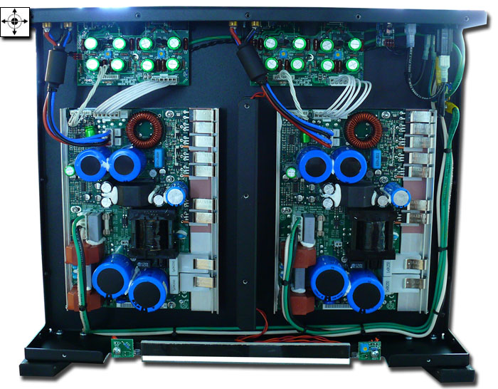
And also note the "Würth 150 kHz ferrite" ( Split Core Ferrite, 12.5 mm, 150 kHz, 30 MHz: Amazon.com: Industrial & Scientific ) in the following unidentified NCORE build:

....
Given the above, what do people think about the addition of "low frequency emi suppression ferrites" to the output and power-supply cabling before it exits the metal case of an NC400 build?
For details see Ferrite Cores For Low-Frequency EMI Cable Suppression - Fair Rite e.g., FAIR-RITE 2675665702 Frequency Min:200kHz (5 pieces): Amazon.com: Industrial & Scientific
As a counterargument, the SMPS and NC400 seem to have their own ferrite filters and adding more, certainly to the output cabling, could potentially be detrimental.
For example:
https://hal.archives-ouvertes.fr/hal-01103584/document
Discuss...
Perhaps slightly off-topic, and perhaps not, if output or power-supply fs (or multiples thereof) end up leaking back into the amplifier input-- what about adding ferrites to the amp outputs?
For example, with "Wyred for Sound ST500 mkII" (ICEPower) we see
An externally hosted image should be here but it was not working when we last tested it.
( Nord One Up Ncore NC500 amps, Class D ready for prime time ..... - Page 23 )
or
( 6moons audio reviews: Wyred4Sound ST-500 )
And also note the "Würth 150 kHz ferrite" ( Split Core Ferrite, 12.5 mm, 150 kHz, 30 MHz: Amazon.com: Industrial & Scientific ) in the following unidentified NCORE build:
....
Given the above, what do people think about the addition of "low frequency emi suppression ferrites" to the output and power-supply cabling before it exits the metal case of an NC400 build?
For details see Ferrite Cores For Low-Frequency EMI Cable Suppression - Fair Rite e.g., FAIR-RITE 2675665702 Frequency Min:200kHz (5 pieces): Amazon.com: Industrial & Scientific
As a counterargument, the SMPS and NC400 seem to have their own ferrite filters and adding more, certainly to the output cabling, could potentially be detrimental.
For example:
https://hal.archives-ouvertes.fr/hal-01103584/document
"This paper showed that ferrite beads used for EMI suppression
in Class-D amplifier systems, have a non-negligible effect
on the amplifier audio quality. In the time domain, the ferrite bead nonlinear behavior is seen as peaks apparition at voltage
zero crossing. This can be translated to the frequency domain
by an increase of the odd harmonics in the audio frequency
band.
Furthermore, the THD measurements showed the impact
of the ferrite bead on the audio quality for all the tested
frequencies and a wide range of signal amplitudes. The
THD measurements and FFT calculations proved, therefore,
the significant impact of these non-linearities on the audio
performance.
This paper highlights the need of a model taking into account
the ferrite bead non-linear behavior, to help the designers
choose their optimal ferrite bead."
Discuss...
Wow these ferrite beads literally sound like bad news per aforementioned paper Ferrite bead effect on Class-D amplifier audio quality "Kevin El Haddad, Roberto Mrad, Florent Morel, Gael Pillonnet, Christian Vollaire, et al.. Ferrite
bead effect on Class-D amplifier audio quality. IEEE Mediterranean Electrotechnical Conference,
Apr 2014, Beirut, Lebanon. IEEE Mediterranean Electrotechnical Conference, 2014, "
Question: if using a power-supply IEC cord with built-in ferrites, e.g. Amazon.com: Power Cord For Phantom, Phantom DE, and Xtrasun Ballasts, 8', 120V, w/Ferrite Ring, AWG 14/3: Electronics does the zero-crossing hysteresis-effect seen in the diagrams of the above paper cause high-frequency switching noise at multiples of 50-60Hz to be injected into the power supply, which might actually cause more interference than no ferrites at all?? Probably not, right, because at 50-60Hz, even a "low frequency" 150-200kHz ferrite has negligible effect.
Question 2: does the effect described in the above paper occur for the case of a "split core" being wrapped around the power or output cabling twisted-pairs, as opposed to a ferrite bead sitting on each output on the amplifier board itself? Wouldn't the twisted pair cancel out any imparted EM into the ferrite core and therefore the split-core ferrite over twisted-pair scenario would only filter "common mode" noise induced onto both lines simultaneously?
bead effect on Class-D amplifier audio quality. IEEE Mediterranean Electrotechnical Conference,
Apr 2014, Beirut, Lebanon. IEEE Mediterranean Electrotechnical Conference, 2014, "
As can be seen from Fig. 9, the ferrite bead deteriorates
the signal THD in the amplitude range [10 mV - 7 V ]. Ferrite
beads have a negative impact on the audio signals even though
the component current in the range of [1 mA - 737 mA] is
lower than the component rated current which is 2 A. However,
below 10 mV the amplifier output noise does not allow any
comparison. Moreover, Fig. 10 shows that the ferrite bead
increases the THD on the entire frequency range. Note that,
beyond 6.5 kHz the THD measurements decrease suddenly.
This is because some of the odd harmonics are already out of
the audio band.
As a result, the ferrite bead increases the THD of the signal
delivered by the amplifier at all frequencies and a wide range
of signal levels. The deterioration caused by the ferrite bead
can reach −35 dB. Note that, −40 dB of THD level can be
distinguished by the human ear. Thus, the ferrite bead reduces
the audio quality of the amplifier due to its nonlinear effect in
the audio band
Question: if using a power-supply IEC cord with built-in ferrites, e.g. Amazon.com: Power Cord For Phantom, Phantom DE, and Xtrasun Ballasts, 8', 120V, w/Ferrite Ring, AWG 14/3: Electronics does the zero-crossing hysteresis-effect seen in the diagrams of the above paper cause high-frequency switching noise at multiples of 50-60Hz to be injected into the power supply, which might actually cause more interference than no ferrites at all?? Probably not, right, because at 50-60Hz, even a "low frequency" 150-200kHz ferrite has negligible effect.
Question 2: does the effect described in the above paper occur for the case of a "split core" being wrapped around the power or output cabling twisted-pairs, as opposed to a ferrite bead sitting on each output on the amplifier board itself? Wouldn't the twisted pair cancel out any imparted EM into the ferrite core and therefore the split-core ferrite over twisted-pair scenario would only filter "common mode" noise induced onto both lines simultaneously?
Interesting Paper "Pin 1 Revisited" from Rane
Pin 1 Revisited
Pin 1 Revisited
The Neutrik Solution
The European EMC directive, implemented in the late 1990's, places limits on noise emissions from elec-tronic equipment sold in most European countries. It caused a lot of manufacturers to get EMC religion, and gave new life to RF engineers working in labs dedicated to verifying compliance. The engineers, working in these labs and those specializing in designing for good EMC performance, think in terms of RF immunity and computer/digital systems. Few have much practical experience with analog audio systems, and some of the design solutions they advance can cause us considerable grief -- especially the treatment of cable shields.
From an RF point of view, the shell of an XLR connector looks like it should work as the extension of the cable shield. For broadband RF immunity, it can be helpful to ground shields at every opportunity and carefully bond all grounded objects together at multiple points. Such a philosophy is the basis of the so-called “mesh” ground topology, and it can work well in installations where there’s little difference in potential between grounds at opposite ends of the audio paths. But power system leakage currents cause enough power-related shield current to flow in most real world installations to couple noise into the sound system if both ends of a cable shield are grounded.
Since the 1930’s, engineers have known that audio frequency noise coupling will be minimized with single point (star) grounding, while radio frequency noise coupling is minimized with multi-point (mesh) grounding. The solution is simple -- the shield of a balanced audio cable is connected to the shielding enclosure at the driving source, and to the shielding enclosure at the receiving end through a capacitor. It was easy to do this in the 40’s, when RF signals higher than 30 MHz were rarely encountered. It’s much tougher now, when the interference sources are strong RF signals from UHF cell phones and high power TV transmitters. Again, it’s series inductance that makes life difficult, this time the inductance of the capacitor’s wire leads. See Figures 5 and 6.
Figure 5. This is the classic RF pin 1 problem in a mic. The cable shield goes to the enclosure, but through a wire long enough to have significant inductive reactance at VHF. The drop across the inductance is coupled to the signal zero reference, where it is added to the signal.
A circuit configuration that avoids a pin 1 problem
Figure 6. A circuit configuration that avoids a pin 1 problem. The shield goes directly to the shielding enclosure. Signal reference common also goes to the shielding enclosure, but there is no common impedance.
Feed-through capacitors have been a solution to this problem since the 1930’s. They mount in a circular hole in an enclosure. One “plate” of the capacitor is a wire going through the enclosure, while the other “plate” is a cylinder surrounding the wire and connected to the enclosure with a dielectric (insulation) between the plates. This circular construction minimizes the inductance through the capacitor to the chassis enclosure, while the wire coming into the chassis enclosure still has inductance. The resulting electrical circuit is an effective RF filter while it also prevents a hole in the shielding.
To provide the most effective shielding, both cable shields and the shells of connectors within equipment should be bonded to the chassis. (Retired Bell Labs engineer and EMC authority Henry Ott observes that if this connection is to the outside of the enclosure, skin effect will keep RF currents outside the enclosure as well.) But what about cable-mount connectors? To make the EMC engineering community happy, mic cables should tie the cable shield to the connector shell, but to make audio folks happy the shield should go only to pin 1. A few years ago, I proposed the concept of making a cylindrical connection to the shield in cable-mounted connectors much like that in a BNC connector, with that cylinder surrounded by a cylindrical dielectric that was itself surrounded by a cylindrical plate connected to the connector shell. Such construction would form a capacitor having very low series inductance, turning the XLR connector into a two-circuit feed-through capacitor. It would connect the shield to the shell at RF, while isolating it from the shell at audio frequencies and DC. When used on mic cable, the shield is also soldered to pin 1. When used at line level inputs in a rack, an installer could decide not to connect the shield to pin 1, but it would still be connected to the shell at RF through the capacitor.
Engineer Joanne Dow observed that if such a connector were to be used with a connection to pin 1, the capacitor and the series inductance to the chassis through pin 1 would form a parallel resonance, and suggested a ferrite bead surrounding pin 1 in the cable connector to lower the Q of the resonance.
It took a while for these ideas to germinate, but before long, engineers at Neutrik had begun work on a practical implementation (Figure 8), and by early 2002 had developed engineering prototypes. British consultant John Woodgate tested them in his lab, and I tested them both in my lab and in the field. The results met my expectations, and yielded an unexpected bonus -- they solved RF pin 1 problems, even when pin 1 was connected at both ends!
A simple circuit study shows why. Figure 7 shows a cable using the new connectors used with the mic shown in Figure 5. The concentric capacitor ties the shield to the mic shell with an inductance that is much lower than the wire inside the mic.
Figure 7. The new EMC connector as it would be used at both ends of a mic cable. The shield has a DC connection to pin 1 with a ferrite bead around it. The concentric capacitor also connects it to the shell. The ferrite bead increases in series impedance through pin 1 at RF, while the capacitor makes a very low impedance connection of the shield to the equipment (or mic) enclosure.
Neutrik EMC connection
Figure 8. This drawing was produced by Neutrik for my AES paper. A pictorial view of the new EMC connector, courtesy Neutrik.
Not only that, but the ferrite bead around pin 1 inside the new connector adds series impedance to the path through pin 1, effectively disconnecting the shield from the pin 1 problem. Shield current thus divides, most of it taking the low impedance path through the capacitance to the shell, with very little flowing through pin 1. In effect, the new connector bypasses the problem!
But even this well engineered solution cannot be effective if mating connector shells don’t make good contact, or if the equipment connector shell is not bonded to the enclosure. I own a portable DAT machine that has a massive pin 1 problem, so much so that when it’s used with its own preamp with a dynamic mic in downtown Chicago the detected FM and TV stations are nearly as loud as an interviewer a foot from the mic. The new EMC connector completely eliminates the detected RF -- if I carefully push against the side of the connector to force the connector shells to make contact. But without that pressure, the shells can lose contact and the RF interference returns! And the new connector doesn’t help a popular mixer with a serious RF pin 1 problem, because the equipment connector shell is not connected to the enclosure!
I got to this thread while searching on "input filter for NC400". Having been triggered by this sentence in Bruno Putzey's famous article: "input filters are invariably added to properly designed kit to insure that the music continues in the presence of mobile phones and taxi dispatches". Interestingly enough he did not add an input filter to the NC400, or recommend to do so in the datasheet...
I thought it would be good to add one to mine. Now I'm a bit new in this field, so looking for some validation of my ideas:
- my NC400s have balanced inputs
- my understanding is that I should add a filter to both the "hot" and "cold" inputs
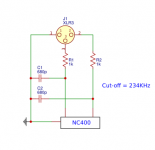
- filter should be directly connected to the XLR input
- cut-off around 250KHz should be low enough and still leaves some headroom if it gets lowered by output impedance of the source
This is the circuit I have in mind:

Can anyone comment on this? Is this the right filter circuit? Should I measure the output impedance of the source before deciding on R value?
I thought it would be good to add one to mine. Now I'm a bit new in this field, so looking for some validation of my ideas:
- my NC400s have balanced inputs
- my understanding is that I should add a filter to both the "hot" and "cold" inputs
- filter should be directly connected to the XLR input
- cut-off around 250KHz should be low enough and still leaves some headroom if it gets lowered by output impedance of the source
This is the circuit I have in mind:
Can anyone comment on this? Is this the right filter circuit? Should I measure the output impedance of the source before deciding on R value?
Attachments
cut off 250kHz? I guess 25kHz (maybe 30) is more appropriate if you are sure that the frequency does not get shifted lower by some source impedance.
Does anybody have UCD 400 / NC400 schematic? I can help you to find the "best place" within the schematic to connect a single cap that acts as a low pass.
Does anybody have UCD 400 / NC400 schematic? I can help you to find the "best place" within the schematic to connect a single cap that acts as a low pass.
In case there is a nice and elegant way to convert the input differential amp into a differential lowpassing amp, you d have a chance to avoid having to insert the series resistors (you cannot know if the higher source impedance has any side effect as long as you do not have the schematic)..
Hi Maartn,
I think I'm trying to achieve the same thing between my prrepro and Hypex 502MP poweramps and I started a thread here: XLR low pass filter between prepro and power amp
Any advice you can offer on capacitor values or if it would work would be much appreciated (I am a complete beginner).")
I think I'm trying to achieve the same thing between my prrepro and Hypex 502MP poweramps and I started a thread here: XLR low pass filter between prepro and power amp
Any advice you can offer on capacitor values or if it would work would be much appreciated (I am a complete beginner).
I think I'm trying to achieve the same thing between my prrepro and Hypex 502MP poweramps
I am also very much an amateur.
Reading your thread, I think your situation is different from what was described here. This thread is about unwanted output frequencies in the audible spectrum (~20 Hz to 20 KHz) caused by input frequencies way above audible (460 KHz and 920 KHz). The cause is a “feature” of the NC400 module.In your case, because different tweeters behave differently, perhaps the cause is somewhere else?
- Status
- This old topic is closed. If you want to reopen this topic, contact a moderator using the "Report Post" button.
- Home
- Amplifiers
- Class D
- Hypex Ncore NC400 - input anti-alias filter?