See also http://www.diyaudio.com/forums/clas...00-input-anti-alias-filter-3.html#post5423090
Ferrite bead effect on Class-D amplifier audio quality
Concluding:
Ferrite bead effect on Class-D amplifier audio quality
As can be seen from Fig. 9, the ferrite bead deteriorates
the signal THD in the amplitude range [10 mV - 7 V ]. Ferrite
beads have a negative impact on the audio signals even though
the component current in the range of [1 mA - 737 mA] is
lower than the component rated current which is 2 A. However,
below 10 mV the amplifier output noise does not allow any
comparison. Moreover, Fig. 10 shows that the ferrite bead
increases the THD on the entire frequency range. Note that,
beyond 6.5 kHz the THD measurements decrease suddenly.
This is because some of the odd harmonics are already out of
the audio band.
As a result, the ferrite bead increases the THD of the signal
delivered by the amplifier at all frequencies and a wide range
of signal levels. The deterioration caused by the ferrite bead
can reach −35 dB. Note that, −40 dB of THD level can be
distinguished by the human ear. Thus, the ferrite bead reduces
the audio quality of the amplifier due to its nonlinear effect in
the audio band
Concluding:
This paper showed that ferrite beads used for EMI suppression
in Class-D amplifier systems, have a non-negligible effect
on the amplifier audio quality. In the time domain, the ferrite
bead nonlinear behavior is seen as peaks apparition at voltage
zero crossing. This can be translated to the frequency domain
by an increase of the odd harmonics in the audio frequency
band.
Furthermore, the THD measurements showed the impact
of the ferrite bead on the audio quality for all the tested
frequencies and a wide range of signal amplitudes. The
THD measurements and FFT calculations proved, therefore,
the significant impact of these non-linearities on the audio
performance.
This paper highlights the need of a model taking into account
the ferrite bead non-linear behavior, to help the designers
choose their optimal ferrite bead.
Where is the phase shift discussed?
************ *************
About the RF/EMI ferrites or filters and class D, some European stores add a chinese filter on the IcePower 1200AS2, but this is other story. Apollon and Rouge Audio.
I have a thread in Audiocircle/All Solid State:
Amplifiers with IcePower 1200AS2, class D module
************ *************
About the RF/EMI ferrites or filters and class D, some European stores add a chinese filter on the IcePower 1200AS2, but this is other story. Apollon and Rouge Audio.
I have a thread in Audiocircle/All Solid State:
Amplifiers with IcePower 1200AS2, class D module
Last edited:
Where is the phase shift discussed?
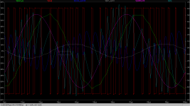
The paper doesn't directly mention phase shift, however, note the troubling zero-crossing "hysteresis" effect:
It can be seen that voltage measured before
the ferrite bead Vin keeps it’s sinusoidal nature. However,
The voltage measured after the ferrite bead, presents some
nonlinear behavior near to zero. According to (??), the voltage
across the ferrite bead is computed and shown in Fig. 6.
As can be seen in Fig. 6,pikes appear when the signal
passes through 0 V
https://hal.archives-ouvertes.fr/hal-01103584/document
Although phase not mentioned specifically, please note Figure 5 showing what appears to be an amplitude-dependent phase-shift from input to output across ferrite, with a discontinuity at zero.
Figure 6 shows the zero-crossing distortion.
Figure 8 shows frequency-domain distortions introduced.
I would like to contribute my experience in sorting this subject:
- Absolute phase (evaluating a single signal) can only become audible at mid and low frequencies. Neurons are not fast enough to characterize phase in high frequency transients.
- Relative phase (evaluating 2 signals) can become audible at any frequency. At high frequencies relative perception depends more on amplitude than on phase. At low frequencies relative perception depends mostly on phase.
- While designing a system there are 2 priorities into play: Good engineering practices (for the conservation of discipline), cost reduction practices (for the conservation budget). Conservation of discipline and budget are mutually opposing.
- There are many shortcuts possible in the design of class-D amplifiers. There is also a general solution. There is not much difference in the cost of the parts. Most of the difference comes from the degree of truth in everyday life required to understand technological solutions. General solution requires more truth to be understood, this has a cost. But past some point higher cost is not necessarily more truth.
- Sound processing without phase shift and/or delay is not possible.
- An amplifier with phase shift proportional to frequency across pass-band acts as a fixed delay. This is good engineering practice. This can be corrected *easily* with delay, for any application. Such a kind of amplifier is a reference design, or basic building block (see 2 pictures attached, showing my reference design).
- Shortcuts in the design of class D amplifiers lead to circuits whose phase shift is not proportional to frequency, and whose frequency response is not flat. This is not good engineering practice (such gear is of no help to conserve discipline). This is budget. This cannot be corrected easily.
- Relative phase is not affected when two amplifiers with same HF phase/amplitude artifacts are used, as long as tolerance in artifacts between amplifiers is satisfactory. Artifacts have to be characterized, with tolerances, to be able to engineer "more system" on top of them. "Amateurs" use shortcuts without tolerance analysis. No way to build professionally on top of that.
- Only two reasons can lead someone to meticulous analysis of phase shift in audio amplifiers. It can be a runaway from lack of knowledge about phase shift and other abnormalities in speaker response. It can be after learning everything about speaker physics.
- In multi-way speaker systems, due to unavoidable minor comb-filter phenomena (residual comb-filtering due to minor sound reflections), changes of just 0.1dB in amplifier+loudspeaker response can be heard.
- Voice coil resistance increases by 1dB (+12%) for each 35C temperature increase (copper), thus reducing response up to -1dB, but not as much at all frequencies, as a loudspeaker has a impedance plot characterized by (Rvc + major/minor resonances + inductance), so phase shift and box tuning are also affected. Even ambient temperature changes of 10C can perceptibly de-tune a precision DSP-tuned multi-way speaker system, at low volume. Listening at moderate volume on Hi-Fi speakers is also enough for detuning. Even worse: different types of music heat more one driver or another in multi-way systems, leading to a type of de-tuning dependent on type of signal!
- Voice coil resistance can change pretty fast in HF drivers. Primary thermal time constant of smaller voice coils, like 1" tweeters, can be in the range of 100ms. This means that the system can become de-tuned and recover as fast as 100ms + 100ms. De-tuning often means shifting of polar pattern, thus cancellations and peaks that go back and forth, and unsteady sound imaging.
The missing gap between amplifier and loudspeaker integration is voice-coil resistance vs. temperature change compensation. As temperature dependency is eliminated, any other artifact becomes constant vs. temperature, thus straight to correct with equalization and delay.
Attachments
Last edited:
NO! Because Icepower is not High-End, many shortcuts against good engineering practice were taken in design. B&O is a company led by money discipline, not by engineering discipline.
But, are you going to start a chase for windmills just because they are noisy and look ugly?
But, are you going to start a chase for windmills just because they are noisy and look ugly?
Last edited:
These days, in a class A amplifier thread there are comments about the phase shift:
Aksa Lender P-mos Hybrid Aleph (ALPHA) Amplifier
Hugh Dean (AKSA)
IcePower 1200AS2 has 50º at 2 kHz. And about 70º at 20 kHz. In other technologies (A and AB) it would be unacceptable. Why not in class D?
I think it is a design flaw but class D is a bit mysterious to me. That is why I opened the thread.
But if it is such a clamorous flaw how is that the graph appears in the manual? -> I decided to open this thread.
Aksa Lender P-mos Hybrid Aleph (ALPHA) Amplifier
Hugh Dean (AKSA)
4. At 1MHz, a typical amplifier would have a phase shift of -100 degrees from the input zero datum point. When this phase shift increases with rising frequency to the magic 180 degrees, somewhere around 2MHz, the negative feedback presented to the inverting input stage amplifier point has effectively now positive feedback...
IcePower 1200AS2 has 50º at 2 kHz. And about 70º at 20 kHz. In other technologies (A and AB) it would be unacceptable. Why not in class D?
I think it is a design flaw but class D is a bit mysterious to me. That is why I opened the thread.
But if it is such a clamorous flaw how is that the graph appears in the manual? -> I decided to open this thread.
Last edited:
NO! Because Icepower is not High-End, many shortcuts against good engineering practice were taken in design. B&O is a company led by money discipline, not by engineering discipline...
AS Series - ICEpower
ICEpower 1200AS2
The 1200AS2 combines a single stage PFC converter with a 2x 1200 W high performance, ICEedge based class D amplifier. Besides extreme audio performance and power it also features monitor outputs for amplifier temperature, voltage and current output. The DC hanger bus can be used for powering additional 300A1 amplifiers. Perfect for professional dual subwoofers, 2-way and 3-way speakers as well as high end consumer active speakers or high-end stereo amplifiers
Somehow you are focusing in a love-hate relationship with something that will not satisfy your expectations. Also running away from another love relationship (with speakers and physics) that could provide more certainty.
Phase shift wise, class D is different from linear because there is a delay involved in modulation, and sharp LPF is required above 20Khz for clean modulation. However, as I showed, there are approaches to make a class D amplifier act as a fixed delay through audio band.
General solution to class D modulation is phase-shift self-oscillating with post-filter feedback. This can be tuned for flat output impedance, delay and frequency response. This is currently made by Hypex and a few others. The technology I'm developing uses same modulation, but it is more oriented towards high-volume listening, and has been offered to complement their product range.
Last edited:

Pascal M-Pro2
http://www.pascal-audio.com/downloads/M-PRO2_Data_Sheet-2_4.pdf
http://www.pascal-audio.com/downloads/M-PRO2_Data_Sheet-2_4.pdf
An externally hosted image should be here but it was not working when we last tested it.
I usually listen to very good records with high DR. I want EMOTION, live/natural/credible sound and not only spectacular and big soundstage.
Months ago I thought that a possibility to achieve both would be the combination of a class A preamp with SE topology (H2 predominant) + new class D poweramp.
The preamplifier: AKSA's Lender Preamp with 40Vpp Output
Months ago I thought that a possibility to achieve both would be the combination of a class A preamp with SE topology (H2 predominant) + new class D poweramp.
The preamplifier: AKSA's Lender Preamp with 40Vpp Output
Hi maty,
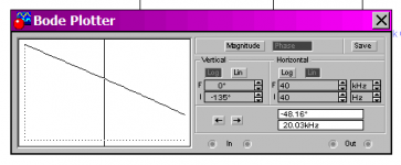
Think you should try look for if they publish another AP graph that show amplitude and phase when amp are driving a real load because the graph you show says up in left corner that its amps output impedance and think members 5th element and DUG already pointed that out, in the end it can happen it will perform flawless in amplitude/phase domain if build as producer suggest of layout and RLC filters or whatever do i know, but also notice that even output impedance increase from 0,005 to 0,050 ohm up at 20kHz its still a low source number and think a phase trace for belonging to that output impedance on a graph has nothing to do with how phase will look over in amplitude domain.
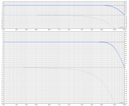
Also at a first look then how scales are presented can sometimes get stuff looks worse or better compared to other brands scales, below is example of this in they exactly the same showing a 2nd order low pass at 50kHz.
Good enough intensions there : ) but think in situation documented speaker acoustic performance count up to 100 times more than amplifier to get into recording room of those very good records with high DR doesn't it.
Think you should try look for if they publish another AP graph that show amplitude and phase when amp are driving a real load because the graph you show says up in left corner that its amps output impedance and think members 5th element and DUG already pointed that out, in the end it can happen it will perform flawless in amplitude/phase domain if build as producer suggest of layout and RLC filters or whatever do i know, but also notice that even output impedance increase from 0,005 to 0,050 ohm up at 20kHz its still a low source number and think a phase trace for belonging to that output impedance on a graph has nothing to do with how phase will look over in amplitude domain.
Also at a first look then how scales are presented can sometimes get stuff looks worse or better compared to other brands scales, below is example of this in they exactly the same showing a 2nd order low pass at 50kHz.
I usually listen to very good records with high DR. I want EMOTION, live/natural/credible sound and not only spectacular and big soundstage.
Months ago I thought that a possibility to achieve both would be the combination of a class A preamp with SE topology (H2 predominant) + new class D poweramp.
The preamplifier: AKSA's Lender Preamp with 40Vpp Output
Good enough intensions there : ) but think in situation documented speaker acoustic performance count up to 100 times more than amplifier to get into recording room of those very good records with high DR doesn't it.
Attachments
Last edited:
ICEpower 1200AS2
[PDF] https://icepower.dk/download/5748/
Search: phase
8 Electrical Specifications
8.2 Speaker Output Voltage and Current Monitors
φ Vmon Voltage monitor phase response f in = 20 Hz - 20 kHz +0/-15 deg
φ Imon Current monitor phase response f in = 20 Hz - 20 kHz +5/-10 deg
10 Typical Performance Characteristics
10.6 Output Impedance
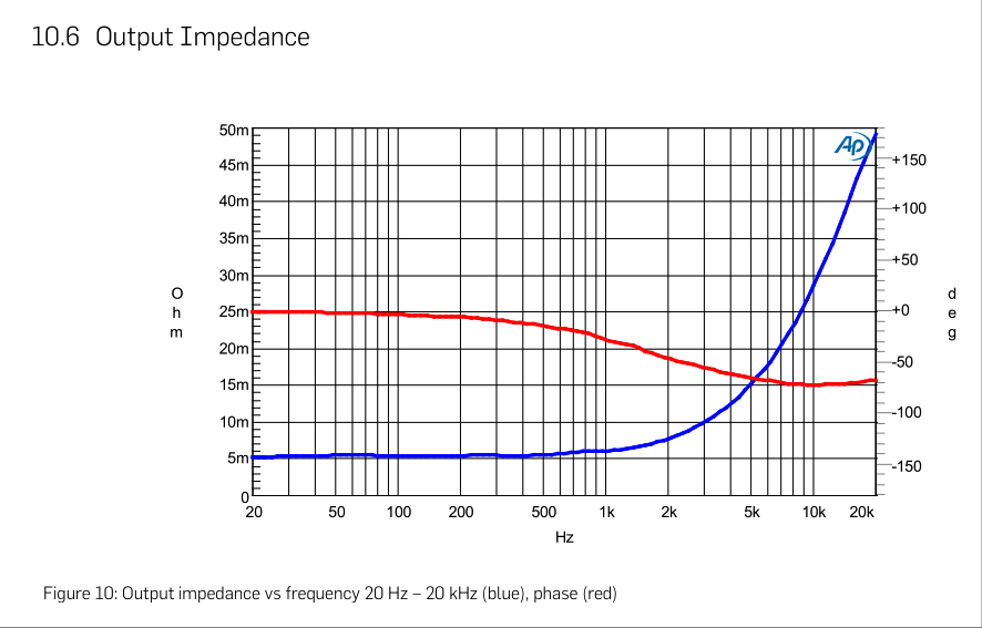
Figure 10: Output impedance vs frequency 20 Hz – 20 kHz (blue), phase (red)
11 Functional Description
11.6.1 Vmon1 and Vmon2 Output
The Vmon1 and Vmon2 outputs are amplitude and phase true representations of the speaker connector output voltage in channel 1 and channel 2 respectively. The Voltage monitor output gain A Vmon, as specified in Section 8.2, is designed so that a full scale unclipped audio signal on the speaker outputs can be presented within the Vmon output voltage range.
For the 1200AS1 module, the Vmon2 output is left unconnected.
Vmon1 and Vmon2 are analog outputs. Interface schematics can be found in Section 12.2. To get best possible signal to noise ratio on the Vmon outputs, it is recommended to use a differential input on the front-end board and use the respective GNDS as ground sense.
11.6.2 Imon1 and Imon2 Output
The Imon1 and Imon2 outputs are amplitude and phase true voltage representations of the speaker connector output current in channel 1 and channel 2 respectively. The current sense circuit is based on a very low valueseries sense resistor in the amplifier speaker output followed by a gain stage. The resulting equivalent current sense resistor, as specified in Section 8.2, is designed so that the current flowing in the speaker output when driving a full scale unclipped audio signal into the minimum specified load impedance can be represented within the Imon output voltage range.
For the 1200AS1 module, the Imon2 output is left unconnected.
Imon1 and Imon2 are analog outputs. Interface schematics can be found in Section 12.2. To get best possible signal to noise ratio on the Imon outputs, it is recommended to use a differential input on the front-end board and use the respective GNDS as ground sense.
[PDF] https://icepower.dk/download/5748/
Search: phase
8 Electrical Specifications
8.2 Speaker Output Voltage and Current Monitors
φ Vmon Voltage monitor phase response f in = 20 Hz - 20 kHz +0/-15 deg
φ Imon Current monitor phase response f in = 20 Hz - 20 kHz +5/-10 deg
10 Typical Performance Characteristics
10.6 Output Impedance
Figure 10: Output impedance vs frequency 20 Hz – 20 kHz (blue), phase (red)
11 Functional Description
11.6.1 Vmon1 and Vmon2 Output
The Vmon1 and Vmon2 outputs are amplitude and phase true representations of the speaker connector output voltage in channel 1 and channel 2 respectively. The Voltage monitor output gain A Vmon, as specified in Section 8.2, is designed so that a full scale unclipped audio signal on the speaker outputs can be presented within the Vmon output voltage range.
For the 1200AS1 module, the Vmon2 output is left unconnected.
Vmon1 and Vmon2 are analog outputs. Interface schematics can be found in Section 12.2. To get best possible signal to noise ratio on the Vmon outputs, it is recommended to use a differential input on the front-end board and use the respective GNDS as ground sense.
11.6.2 Imon1 and Imon2 Output
The Imon1 and Imon2 outputs are amplitude and phase true voltage representations of the speaker connector output current in channel 1 and channel 2 respectively. The current sense circuit is based on a very low valueseries sense resistor in the amplifier speaker output followed by a gain stage. The resulting equivalent current sense resistor, as specified in Section 8.2, is designed so that the current flowing in the speaker output when driving a full scale unclipped audio signal into the minimum specified load impedance can be represented within the Imon output voltage range.
For the 1200AS1 module, the Imon2 output is left unconnected.
Imon1 and Imon2 are analog outputs. Interface schematics can be found in Section 12.2. To get best possible signal to noise ratio on the Imon outputs, it is recommended to use a differential input on the front-end board and use the respective GNDS as ground sense.
Last edited:
About - ICEpower
ICEpower HQ info@icepower.dk
Subject: IcePower 1200AS2 and phase shift, again
ICEpower HQ info@icepower.dk
Subject: IcePower 1200AS2 and phase shift, again
Hi from Spain,
Two weeks ago I send you a mail with a question about the phase shift of IcePower 1200AS2 module.
I opened a thread about the question here in Diyaudio.com
Phase shift in class D amplifiers. How it affects the sound?
Phase shift in class D amplifiers. How it affects the sound?
[URL]http://maty.galeon.com/WP-imagenes/hard/IcePower-1200AS2-output-impedance-phase.png[/URL]
Simple question: Is the output phase of the IcePower 1200AS2?
If not, which?
Please[/QUOTE]
- Home
- Amplifiers
- Class D
- Phase shift in class D amplifiers. How it affects the sound?