OK, can be disturbance from the Bluetooth.
NO Bluetooth connected, CHEAP speakers at the outputs: if you touch on C1 and C11 (diagram above) with a very small screw-driver (careful not to make any short-circuits) on the side toward to Bluetooth, can you hear hum in the CHEAP speakers? (This is my first test "is it alive?")
NO Bluetooth connected, CHEAP speakers at the outputs: if you touch on C1 and C11 (diagram above) with a very small screw-driver (careful not to make any short-circuits) on the side toward to Bluetooth, can you hear hum in the CHEAP speakers? (This is my first test "is it alive?")
I have 19 volt on ic1 between pins 2,3 and 8,9
But only with Bluetooth connected?
But only with Bluetooth connected?
Yes, but the music must also be playing.
Only bluetooth connection and no music playing, then there is no high voltage on the pins.
when i stream the music from my phone to the board, then the voltage goes high.
and only on the right channel.
I have the board examend very well, and don't see any shorts on the circuit board, or components that are wrong soldered.
Hi dutchronnie
Did you made this mods in this thread?
How to prevent popping sound on power on on TDA7492P Amp?
Last edited:
Did you made this mods in this thread?
How to prevent popping sound on power on on TDA7492P Amp?
No.
I did the modifications with an previous board. that board didn't have this problem.
So this modification isn't the cause of the problem with the high voltage on the Right channel.
maybe i am wrong ....i found something in the datasheet (same pic as you posted)
.. if you look at the pic from the input e.g. INNB + INPB and then follow the lines to the J1...its wrong gnd and signal is mixed!...look at the circles....mybe something happend there???
chris
.. if you look at the pic from the input e.g. INNB + INPB and then follow the lines to the J1...its wrong gnd and signal is mixed!...look at the circles....mybe something happend there???
chris
Attachments
Last edited:
No.
I did the modifications with an previous board. that board didn't have this problem.
So this modification isn't the cause of the problem with the high voltage on the Right channel.
ok...just to notice its not..
Maybe, i take a look at it this when i am home again.
It's strange, both board have exactly the same number, they look the same so why should one board the INPB an INNB been switched ?
hm.. i am not the expert...yes it is strange.
i ´m just follow the datasheet (page 5) from output back to the "source"
Attachments
Sorry for not being on the forum regularly these days.
When your Bluetooth is connected, you have 19V (12V) DC on one channel while the other works.
Without much surprise, it can be the chip itself or the way the chip is used (including failure of an external component).
It is important to know if the 19V (12V) is due to the Bluetooth (fault at the input) or it is the amplifier itself. This was why I suggested you to try (without the Bluetooth connected) to put a very small screwdriver on the input coupling capacitors and hear if you have hum in the CHEAP speakers.
If you do have hum in both speakers, the TDA7498 amplifier is likely to work and the Bluetooth may be the culprit. If you do not have hum in any of the speakers, it is likely that the TDA7498 is in standby/muted by the Bluetooth until the Bluetooth is connected.
If so, when the amplifier part is activated, the 19V (12V) appears because both channels are activated. To find out what is wrong with the amplifier, when activated, requires check of the signals on the chip pins. When you have two channels and one works, you can compare the signals and levels on corresponding pins. If the input pins are at different levels, we can narrow our search to the input circuit. If the input pins are at very similar levels, the 19V (12V) is likely to be from an internal TDA7498 fault.
Could you do first the hum test (no Bluetooth connection, CHEAP speakers at the outputs)?
Then, with an 8Ohm dummy resistor on the channel that works and an 1KOhm resistor on the 19V (12V) channel, could you measure the DC voltages (to ground) on TDA7498 pins 20, 21, 22, 23, 28, 32 and 33 with a multimeter?
Hello Fauxfrench,
Sorry, i didn't understand your first reaction, but now i do.
I tried the thing you mentioned.
First the cheap speaker, but i didn't hear any hum
i hear a little noise, on both channels, but no change when i touch the capicitors.
then i put the resistors on the outputs. 8 ohm and 1k ohm.
this are the results i measured, with bluetooth from the phone connected.
20 - 3.195 volt
21 - 1.794 volt
22 - 2.076 volt
23 - 2.076 volt
28 - 0.002 volt
32 - 4.200 volt
33 - 2.715 volt
This with a power source of 12 volt
Pins 23 and 33 correspond to one another, but, the voltages are (different) 2.1V – 2.7V
Pins 22 and 32 correspond to one another, but, the voltages are (different) 2.1V – 4.2V
Pin 28 is the diagnosis pin with 0.0V on it.
Pin 20 is the STANDBY pin with 3.2V on it.
Pin 21 is the MUTE pin with 1.8V on it.
Comments:
Pins 22/23 and 32/33 →
Pins 22/23 (channel A) have the same voltage on them and the loop is likely to be in regulation. My guess is that the output from pins 10,11,16,17 is the output that works?
Pins 32 and 33 (channel B) have a very different voltage on them (and different from pins 22 and 23) such that the regulation does not work at all. My guess is that the output from pins 2,3,8,9 is the output with 19V (12V) on it?
Pin 28 is the DIAGNOSIS output. According to the datasheet, it is low if there is a fault OR because the pull-up resistor has not been mounted. Let’s leave that aside for a moment.
Pin 20 is the STANDBY pin, using 3.3V logic signals, and with 3.2V on it it is unambiguously “high” which means (datasheet, Table 7) NOT in standby mode. Fine.
Pin 21 is the MUTE pin, using 3.3V logic signals, and with 1.8V on it, it is in a gray zone between LOW and HIGH (page 9 datasheet; gray zone between 0.8V and 2.5) where we have no guarantee for how the chip reacts. This is absolutely not OK and it may be that one channel interprets this as no mute while the other freaks out with 19V (12V). A first flaw to repair!
The MUTE pin is probably controlled by the Bluetooth circuit but in an insufficient manner. Now we want to know if the amplifier still works, so, we force the MUTE pin “high” to see if the second output also works. Forcing it “high” means pulling it up with a 4.7KOhm resistor to 3.3V. Here you have to help me identifying the 3.3V voltage regulator because the photo I have is too small to see details. The 3.3V voltage regulator is likely to be the 3 pin IC next to the big “101” resistor. The 220uF/6.3V electrolytic SMD capacitor (next to the big “101” resistor as well) is likely to be connected to the output of the 3.3V voltage regulator.
Please check if this is right (NO Bluetooth connection/ 8Ohm dummies at the outputs)?
When we have found the 3,3V output, we have to find the capacitor being connected between pin 21 and ground (probably2.2uF in value). When that one is found, a small 4.7KOhm resistor has to be soldered between the pin 21 PCB track (at the capacitor) and the 3.3V output line. Use a very fine soldering tip and be quick – it is only for temporary use.
Then comes an exiting but rapid test:
NO Bluetooth connection, 8Ohm dummies at the outputs.
Connect the voltmeter to the channel (probably channel B) which is until now defect (19V/12V) and put the voltmeter in a 20V DC range.
Then you have to be quick → Power ON , is the voltage on the voltmeter above 1 Volt? If yes, switch OFF the power supply as quick as possible. If below 50mV it is likely to work. In between 50mV and 1V we have to see.
Please do the above to see if it is the MUTE voltage that causes the problem and if the amplifier chip still works.
Last edited:
Fauxfrench, Thanks for your great help.
I measured again the board, and i have not a voltage on pin 21.
When i examend the board i saw that there are no components on pin 21, and also on pin 20. they endid on the board on a hole.
Maybe this pins are not used.
You can see it on this photograph:
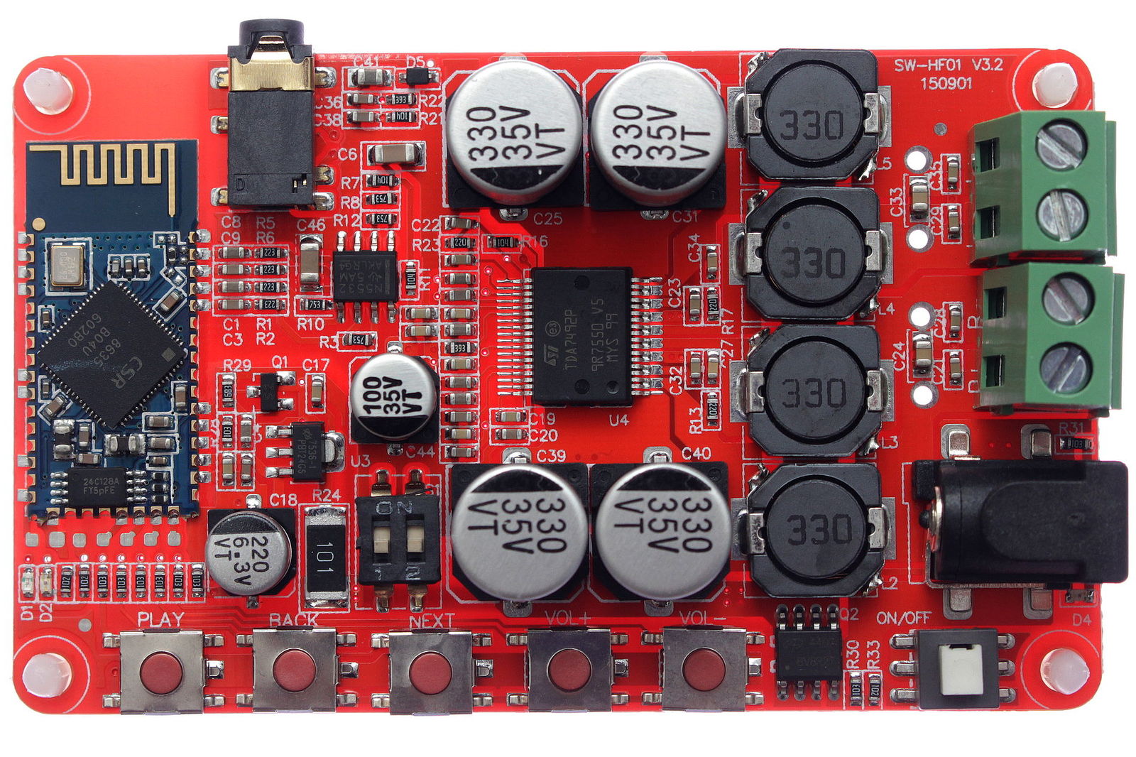
I measured again the board, and i have not a voltage on pin 21.
When i examend the board i saw that there are no components on pin 21, and also on pin 20. they endid on the board on a hole.
Maybe this pins are not used.
You can see it on this photograph:
The small holes are "via"s, thus, small connection holes (conductive) connecting a track on one side with a track on the other side. If you disconnect the power to the board and measure with an Ohm-meter from each of the pins to ground you should measure less than 200KOhm for each pin. Both these two pins HAVE to be tied to ground or "high", they cannot be left floating!
When i measure ohm on pin 20, it begins with 2 M ohm, and increases to more than 3 M ohm in 10 seconds, it goes slowly up.
on pin 21 i measure a steady 2,5 M ohm.
I put a 4,7Kohm resistor between pin 21 and 3,3 volt, turn on the amp, and see 12 volt on the meter. turned off directy power supply
on pin 21 i measure a steady 2,5 M ohm.
I put a 4,7Kohm resistor between pin 21 and 3,3 volt, turn on the amp, and see 12 volt on the meter. turned off directy power supply
- Status
- This old topic is closed. If you want to reopen this topic, contact a moderator using the "Report Post" button.
- Home
- Amplifiers
- Class D
- No sound from TDA7492P Amp