I have two Sure amplifiers that have problems.
AA-AB013V120: This one has never done it. I have used different power supplies. The Hmute light is on indicating there is a problem.
AA-AB32971: This one I bought recently. It sounded very good with this power supply Gratis Verzending 240 w 24 v 10a Enkele Output schakelende suppy in Gratis Verzending 240 w 24 v 10a Enkele Output schakelende suppy van Stroomvoorziening op AliExpress.com | Alibaba Groep
Unfortunately one of the channels suddenly failed and a red light on the board is indicating an error occured.
In both cases the manual gives no information what to do. Any suggestions from this forum?
A lot of these power supplies are intended for powering LED lights. This means that their dynamic (transient) behavior may not be suited for audio amplifiers. With sudden changes in in the current consumption of the amplifier (caused by transients in the music) the output voltage may vary a lot. And, such supply voltage variations may cause voltage spikes to be generated in the amplifier that can destroy the amplifier chip.
Power amplifiers normally need good size power decoupling capacitors preferably on the amplifier board, alternatively at the output of the power supply.
Your AA-AB32971 has got 6 times 470uF in total just below 3000uF for decoupling of a 2x100W amplifier. Clearly insufficient for more loud music.
Your power supply has probably got a current source characteristic with voltage limitation of 24V. If so you could have put some 15000uF-20000uF at the output to stabilize the supply voltage. But, it may be too late now.
For a start, remove the fan and see what kind of switch-bridge is used (it is the small black IC that is being cooled by the heatsink and fan). It is likely to be a STA505, STA508 or something like that.
Do you have a multimeter?
The way I know to find a fault in a monolithic class D amplifier (bridge coupled) is to measure with a multimeter, put in the 20KOhm range, all permutations of the 4 output terminals and the 2 power supply terminals. If any of these combinations give a multimeter reading of less than 10 Ohm steady state the fault is likely to have been found.
Be aware that measuring across the two power supply terminals should give readings that steadily increase when the power line decoupling capacitors are recharged.
If you want to see how a switch-bridge IC of the type you may have on your board, and the IC that may be defect, looks give DIYBudgetAudio.com a glance under the article "TK2050 based class D power amplifier". The so called TK2050 is likely to be the chip-set combination in your Sure amplifier.
It may be this IC that is defect in your amplifier. Dare you give repair a try if that turns out to be the defect IC?
I can tell you how I do (with success until now) but it is not trivial due to the very small dimensions.
Thanks for your quite extensive answer. I tried to remove the fan but need a special device for the screws. But removing the fan won't be enough, removing the cooling block is needed to get access to the chips.The way I know to find a fault in a monolithic class D amplifier (bridge coupled) is to measure with a multimeter, put in the 20KOhm range, all permutations of the 4 output terminals and the 2 power supply terminals. If any of these combinations give a multimeter reading of less than 10 Ohm steady state the fault is likely to have been found.
Be aware that measuring across the two power supply terminals should give readings that steadily increase when the power line decoupling capacitors are recharged.
If you want to see how a switch-bridge IC of the type you may have on your board, and the IC that may be defect, looks give DIYBudgetAudio.com a glance under the article "TK2050 based class D power amplifier". The so called TK2050 is likely to be the chip-set combination in your Sure amplifier.
It may be this IC that is defect in your amplifier. Dare you give repair a try if that turns out to be the defect IC?
I can tell you how I do (with success until now) but it is not trivial due to the very small dimensions.
I measured the resistance between the different connections. They all have high values, nothing close to 10 ohm, even the failing channel.
Its a good suggestion to increase the output capacity of the power supply. But to be honest I can't imagine that this was the reason as the amplifier failed at a low music level. For me no Sure devices any more.
If there is no short circuit (internally) of the 6 terminals there is a chance that the chip is still alive.
A particular “chip killer” in class D amplifiers are the output filter chokes that can generate very nasty voltage spikes if the supply voltage is not stable or too much current is drawn for the outputs. I have seen a TDA8954 chip die from operation at 2x15V with a 1A limit. But, your output switches seem still to be intact.
Then, next step is probably measurement of the signals on each pin of the bridge IC with an oscilloscope. But, that also requires you have access to the IC and the cooling block is removed. If it is glued onto the chip it is very difficult to remove without damaging the PCB.
Be very careful not to short circuit more pins with the probe tip.
If you can get access to the switch-bridge IC and your hands on an oscilloscope, then: a sine-wave on the inputs, cheap 8 Ohm dummy loads or cheap speakers at the outputs and a moderate 15V supply voltage. If one channel still works you can compare the signals for each channel.
Another reason for the faulty channel can be that SMD components break or loose connection in a way that is very difficult to see without a magnifying glass
I guess that also Sure Electronics mainly gets their products from Far East where most is produced nowadays. If the amplifier used to work, it has passed QC and the fault may be due to something else than an obvious design mistake. But, I understand your disappointment – two good amplifiers lost. I tried to find the first amplifier you mention (AA-AB013V120) but I got no matches on the Internet.
Succes!
Thanks again for your answers. I'm afraid I have to take my loss. Besides Sure I now know the service level of loudspeakerfreaks.com where I buyed the board: They don't give any reply on my e-mails and don't answer the phone.If there is no short circuit (internally) of the 6 terminals there is a chance that the chip is still alive.
A particular “chip killer” in class D amplifiers are the output filter chokes that can generate very nasty voltage spikes if the supply voltage is not stable or too much current is drawn for the outputs. I have seen a TDA8954 chip die from operation at 2x15V with a 1A limit. But, your output switches seem still to be intact.
Then, next step is probably measurement of the signals on each pin of the bridge IC with an oscilloscope. But, that also requires you have access to the IC and the cooling block is removed. If it is glued onto the chip it is very difficult to remove without damaging the PCB.
Be very careful not to short circuit more pins with the probe tip.
If you can get access to the switch-bridge IC and your hands on an oscilloscope, then: a sine-wave on the inputs, cheap 8 Ohm dummy loads or cheap speakers at the outputs and a moderate 15V supply voltage. If one channel still works you can compare the signals for each channel.
Another reason for the faulty channel can be that SMD components break or loose connection in a way that is very difficult to see without a magnifying glass
I guess that also Sure Electronics mainly gets their products from Far East where most is produced nowadays. If the amplifier used to work, it has passed QC and the fault may be due to something else than an obvious design mistake. But, I understand your disappointment – two good amplifiers lost. I tried to find the first amplifier you mention (AA-AB013V120) but I got no matches on the Internet.
Succes!
I will install me some capacitors (2*10000uF electrolytical capacitor) to avoid the risks of the power supply with some new amplifier boards I ordered: Dual Channel Audio Stereo Versterker Boord XH M510 TDA7498 DC 14 34 V Versterker Boord van Klasse D 2X100 W in Dual Channel Audio Stereo Versterker Boord XH-M510 TDA7498 DC 14-34 V Versterker Boord van Klasse D 2X100 W van Geintegreerde Schakelingen op AliExpress.com | Alibaba Groep
Not so much hits on the first amplifiers, but this is it: https://www.parts-express.com/pedocs/manuals/320-300-sure-electronics-aa-ab32181-manual-43666.pdf
Last edited:
Power amplifiers normally need good size power decoupling capacitors preferably on the amplifier board, alternatively at the output of the power supply.
Your AA-AB32971 has got 6 times 470uF in total just below 3000uF for decoupling of a 2x100W amplifier. Clearly insufficient for more loud music.
Your power supply has probably got a current source characteristic with voltage limitation of 24V. If so you could have put some 15000uF-20000uF at the output to stabilize the supply voltage. But, it may be too late now.
Erm, that's the size you need on a conventional (transformator) power supply. On the high frequency loading of the SMPS, you need a lot less, it has to buffer for a much, much shorter time. 4-5000µF is really enough with a SMPS.
I will install me some capacitors (2*10000uF electrolytical capacitor) to avoid the risks of the power supply with some new amplifier boards [...]
You got a SMPS (switch mode power supply), it creates a DC voltage, chops it up at a high frequency, transforms and rectifies it again. The problem here is the high frequency, the load cycles are very short. That means, the ripple-current is quite high. If the capacitor isn't an low-ESR type, it heats up the capacitor which drasically shortens its lifetime. If it gets much too hot the capacitor can even burn or explode. So while big capacitors solve the one problem, you need low-ESR capacitors for that. If the power supply already killed 2 amps (and it didn't happen because of a cross-short of the outputs), I would suggest you just buy a different power supply which is proven to behave well, i.e. a Mean Well.
Thanks for your suggestions. Adding a low-ESR capacitor is not a problem but I spotted 3 * 1000uF on the board of the output of the smps.You got a SMPS (switch mode power supply), it creates a DC voltage, chops it up at a high frequency, transforms and rectifies it again. The problem here is the high frequency, the load cycles are very short. That means, the ripple-current is quite high. If the capacitor isn't an low-ESR type, it heats up the capacitor which drasically shortens its lifetime. If it gets much too hot the capacitor can even burn or explode. So while big capacitors solve the one problem, you need low-ESR capacitors for that. If the power supply already killed 2 amps (and it didn't happen because of a cross-short of the outputs), I would suggest you just buy a different power supply which is proven to behave well, i.e. a Mean Well.
I didn't use this power supply for the first failing amplifier. I tested this one using a 12V battery. I think the first amplifier was already failing when I received it (buyed it second hand).
The power supply did it very well even on the highest levels before the second amplifier failed on a low level. I'm in doubt amortizing this power supply and buying a new one.
Fully right that the decoupling proposed by me relates to unregulated 50z/10ms (double rectified) power supplies. And, if you use a good (fast) SMPS or a good quality laboratory power supply they can regulate in less than 10ms. But, with the (probably simple) SMPS shown (likely to be intended for LED lights) or power adapters intended to charge laptops, they may have a slow regulation loop. Both LED lights and laptop batteries are very static loads and a slow regulation loop is cheaper to implement and remains stable with an increased range of loads.
You can try the actual power supply out with an oscilloscope and load-switching but then the work becomes more cumbersome.
This is why I normally use 4700uF-20000uF to be sure, for the moderate costs (compared to the amplifier).
When you have a solid bass transient (like a prominent bass drum) you need the charge to be available for the amplifier, either by charge available in the decoupling capacitors or charge quickly made available by the regulated power supply.
Last edited:
I didn't use this power supply for the first failing amplifier. I tested this one using a 12V battery. I think the first amplifier was already failing when I received it (buyed it second hand).
The power supply did it very well even on the highest levels before the second amplifier failed on a low level. I'm in doubt amortizing this power supply and buying a new one.
That's not impossible but not likely and I doubt with that description it's the fault of the power supply. I'm really sorry if I start that again and might annoy you with it - but are you absolutely sure you did not connect the - of the amp with the enclosure or ground? A friend wanted to measure his amp and it failed while measuring it with a scope. He was so adamant he did not short the output, I had then a look onto his setup. He was using one channel of the scope on the input, the second on the output, to compare them. What happened? The short was completed with the ground/negative of the probe, it connected the bridged output with the shielding, which in turn, was connected on the board to the - of the power supply. Another time he connected the - to the enclosure, ofcourse with the same result.
To taita:
Your first amplifier seems to be real TK2050, thus, genuine Tripath with TP2050 bridges. Very low THD (if it worked).
If there are no screws holding the heatsink, it is likely to be glued to the ICs with thermal glue and then very difficult to remove. It is perhaps possible, as described in the article, but with a risk that the copper tracks on the PCB will be damaged.
Did you do the 10 Ohm test on this board?
That's not impossible but not likely and I doubt with that description it's the fault of the power supply. I'm really sorry if I start that again and might annoy you with it - but are you absolutely sure you did not connect the - of the amp with the enclosure or ground? A friend wanted to measure his amp and it failed while measuring it with a scope. He was so adamant he did not short the output, I had then a look onto his setup. He was using one channel of the scope on the input, the second on the output, to compare them. What happened? The short was completed with the ground/negative of the probe, it connected the bridged output with the shielding, which in turn, was connected on the board to the - of the power supply. Another time he connected the - to the enclosure, ofcourse with the same result.
Thanks for helping to find the root cause. I didn't shorted the outputs of the amplifier, I use an additional terminal to connect the speaker cables to the small amplifier terminals and changed nothing on this when the second amplifier failed. But I am thinking of another experiment I did. I have problems with a Zero DAC that is buzzing and I thought this might be a grounding issue. So I connected the ground of the DAC (the RCA plug outside) with the ground (the metal housing) of the power supply. Nothing happened, de DAC keeps buzzing and the amplifier kept playing, so I disconnected this. A day later one of the amplifier channels failed.
To come back to the power supplies. I examined some of Meanwell but found no specific audio smps. Alle power supplies are for general purpose (LED and electronic equipment) the same as the one I have. Do you recommend a specific type?
To taita:
Your first amplifier seems to be real TK2050, thus, genuine Tripath with TP2050 bridges. Very low THD (if it worked).
If there are no screws holding the heatsink, it is likely to be glued to the ICs with thermal glue and then very difficult to remove. It is perhaps possible, as described in the article, but with a risk that the copper tracks on the PCB will be damaged.
Did you do the 10 Ohm test on this board?
I did the 10 ohm test on this board: everything was high.
I succeeded in removing the heatsink by turning it a little. I found two PCB's that look fine. To be honest I think the problem with this board is not the PCB, but an errouneous design of the activation of the amplifier.
On the power supply: Finding one explicitly for audio use is difficult. Therefore, I use an ordinary (standard) power adapter (outline as a laptop charger) and connect the 10000uF at the output. Only in few cases did I have a bit of hum in the speakers, probably due to the combination with other power adapters for my DAC and headphone amplifier (being used as pre-amplifier with volume control).
Last edited:
Thanks for helping to find the root cause. I didn't shorted the outputs of the amplifier, I use an additional terminal to connect the speaker cables to the small amplifier terminals and changed nothing on this when the second amplifier failed. But I am thinking of another experiment I did. I have problems with a Zero DAC that is buzzing and I thought this might be a grounding issue. So I connected the ground of the DAC (the RCA plug outside) with the ground (the metal housing) of the power supply. Nothing happened, de DAC keeps buzzing and the amplifier kept playing, so I disconnected this. A day later one of the amplifier channels failed.
For how long did the buzzing of the DAC play? Did you let the amp on but idle for an extended period of time? If it went to standby, the power consumption is very low, not every power supply likes that, I've seen some which got voltage spikes without or with extremely low loads.
To come back to the power supplies. I examined some of Meanwell but found no specific audio smps. Alle power supplies are for general purpose (LED and electronic equipment) the same as the one I have. Do you recommend a specific type?
I would recommend the LRS-150-24 (24V) or another of the series for the smaller amps (<75W), they got short circuit, overload, over voltage and over temperature protection and they are pretty cheap too. These PSs need ventilation openings in the enclosure, like almost all PSs.
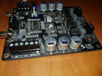
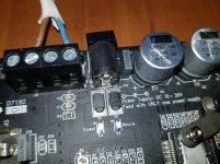
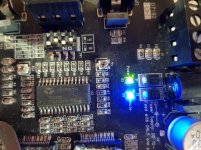
It's some time ago, but I spend some time now on the Tripath amplifier. I removed the heatsink and discoverd a Tripath TC2000 chip. All channels measure an impedance of kilo-ohms, no low values. So I think the amplifier is fine but I have to solve the annoying hmute issue. I enclosed some pictures of the amplifier. There is a mute port and I have shorted this with the 5V port and the ground but the hmute led keeps blue. Any ideas how to solve this?To taita:
Your first amplifier seems to be real TK2050, thus, genuine Tripath with TP2050 bridges. Very low THD (if it worked).
If there are no screws holding the heatsink, it is likely to be glued to the ICs with thermal glue and then very difficult to remove. It is perhaps possible, as described in the article, but with a risk that the copper tracks on the PCB will be damaged.
Did you do the 10 Ohm test on this board?
Attachments
Let's give it a try.
The TC2000 chip you found is the modulator. The two chips with thermal grease are probably TP2050 or STA505. Will you please check? They all have mute/disable pins and fault indication pins.
What is your supply voltage?
I had to check the datasheets for the interesting pins:
TC2000:
Pin 8 (output): Logic high means muted or fault discovered.
Pin 18 (output): Low indicates input to be out of range.
Pin 19 (input): Over-/under-voltage setting resistor.
Pin 24 (input): High or floating leaves outputs muted. Only low ensures operation.
TP2050
Pin 24 (input): Must be high for parallel operation.
Pin 25 (input): Stand-by, must be high for operation.
Pin 26 (input): Tri-state, must be high for operation.
Pin 27 (output): Fault, must be high, indication of fault if pulled low .
Pin 28 (output): Thermal warning output, low if overheated.
Please do all your tests with power using dummy resistors at the output. An unloaded output may destroy the TP2050 chips!
Will you please check if the pin voltages are as shown above?
The question is if the “mute” lamp on your board is turned on by an output pin on the TC2000 (probably pin 8) or an output pin on a TP2050 (probably pin 27) or something else.
Can you figure out by what that lamp is controlled?
Thanks for your answer. On your questions:Let's give it a try.
The TC2000 chip you found is the modulator. The two chips with thermal grease are probably TP2050 or STA505. Will you please check? They all have mute/disable pins and fault indication pins.
What is your supply voltage?
I had to check the datasheets for the interesting pins:
TC2000:
Pin 8 (output): Logic high means muted or fault discovered.
Pin 18 (output): Low indicates input to be out of range.
Pin 19 (input): Over-/under-voltage setting resistor.
Pin 24 (input): High or floating leaves outputs muted. Only low ensures operation.
TP2050
Pin 24 (input): Must be high for parallel operation.
Pin 25 (input): Stand-by, must be high for operation.
Pin 26 (input): Tri-state, must be high for operation.
Pin 27 (output): Fault, must be high, indication of fault if pulled low .
Pin 28 (output): Thermal warning output, low if overheated.
Please do all your tests with power using dummy resistors at the output. An unloaded output may destroy the TP2050 chips!
Will you please check if the pin voltages are as shown above?
The question is if the “mute” lamp on your board is turned on by an output pin on the TC2000 (probably pin 8) or an output pin on a TP2050 (probably pin 27) or something else.
Can you figure out by what that lamp is controlled?
- The power supply is a 12V battery
- The thermal grease has completely been backed on the surface of the chip. I can't remove it to read the type of chip
Before I read your answer I did some experiments myself. I found the datasheet of the chip TC2000 datasheet(3/9 Pages) TRIPATH | STEREO CLASS-T™ AUDIO CONTROLLER USING DIGITAL POWER PROCESSING (DPP™) TECHNOLOGY and found that pin 24 of the chip has to be grounded to operate. So I did this with a thin wire and the hmute LED went off. Then I made a soldered connection. But when I turned the amplifier on the LED went off but then went on again. And now the hmute LED is on independent if pin 24 is grounded or not. Unfortunately I didn't loaded the output of the amplifier. So probably I repaired it but it is destroyed? I tested the impedance of the output but no low levels there until so far.
- Home
- Amplifiers
- Class D
- Problems Sure amplifiers