Hi Forestsgump
Sorry to read that you are still have this pop on/off problem. as i learned at the TPA3255 YJ board ....... tps3802_supply voltage supervisors "ARK" chip :
there is a chip inside of the FX502Spro to manage this on off behaivour...check maybe the datsheet which values you should have.
chris
Thk Chris for the hint, though I looked hard on FX502Spro board dint find such a chip like "ARK".
These are the list of semiconductors:
Op amp (TI NE5532P)
ST S003F3P6 8bit MCU
IRF9530N
LM2596HVS
AMS1117
LM317M
& ofcourse TPA3250
Any picture to show this chip location?
Last edited:
Hi forestsgump
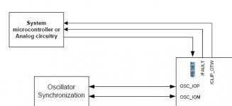
datasheet the figure 22 - its the pin config of the tpa3251 !! it is wrong..i wrote this pages before
look at the picture attached..in the datahseeet is written that the RESET pin5 can be forced with a analoge circuit or a microcontroller...so the ST S003F3P6 8bit MCU is right here..")
so...the only problem is that we have to check which pin of the µC set the pin5 of the tpa3250..and check the datasheet for the "time constant" to do this right...but sorry i lost at the moment with this µC
chris
datasheet the figure 22 - its the pin config of the tpa3251 !! it is wrong..i wrote this pages before
look at the picture attached..in the datahseeet is written that the RESET pin5 can be forced with a analoge circuit or a microcontroller...so the ST S003F3P6 8bit MCU is right here..
so...the only problem is that we have to check which pin of the µC set the pin5 of the tpa3250
..and check the datasheet for the "time constant" to do this right...but sorry i lost at the moment with this µCchris
Attachments
i looked at a pic of my pcb layout on the upper side (white baord)
if you follow the traces tpa3250 pin it looks like that it goes to C55.
because you report from the beginning that you had this pop on/off noise maybe check this region....... what do you have there...resoldering?
chris
if you follow the traces tpa3250 pin it looks like that it goes to C55.
because you report from the beginning that you had this pop on/off noise maybe check this region....... what do you have there...resoldering?
chris
Attachments
found this page that includes some mods done to this amp:
ヤフオク! - NFJ & FX-AUDIO FX502Spro改造品 FX502J-Sの海...
translate says:
I have wadia 151 power dac in my system (diy speakers with beyma 12g40 , 3" dome mid from tang band and amt mundorf tweeter) and just received this amp (fx502spro) and matched it with dac from khadas - tone board (es9038q2m).
After some listening time all i can say it does sound somehow different to my wadia.
Wadia seems to be better in lower freq. bass is more solid and punctual but everything else sound more thin... (please note I also compared wadia to ad18 and to me wadia was also cleaner ,and better choice overall) highs are as well slightly more exposed and wadia seems to be quieter - cleaner...
fx502spro with khadas sounds more boomy at lower freg (dirty, not as controlled) but mids are fuller, the whole sound is more tube like with deeper soundstage where wadia is more direct ,plain cleaner but without this "magic".
I will try to swap some opamps and see how this will change the signature.
ヤフオク! - NFJ & FX-AUDIO FX502Spro改造品 FX502J-Sの海...
translate says:
Parts Changes
, electrolytic capacitor
Date Kemi KZE 35V 330UF → Manufacturer Nichicon Product Category KW 35V 470UF
Manufacturer Nichicon Product Category PW 35V 100UF X 3 → day Kemi KZH 35V 100UF X 3
ELNA 85 degrees goods 25V 10UF X 4 → ELNA RF0 (PureCap) 50V 10UF X 4
-cup coupling capacitors
ELNA 85 ° article 50v 2.2uF x 2 → ERO MKT1813 (axial type metallized polyester) 2.2uF x 2
· LPF
Arcotronics 1.0UF x 4 → ERO MKC1860 (axial type metallized polycarbonate) 0.68UF x 4
· op
NE5532 x 2 → JRC2114DD x 2
polycarbonate film capacitor is also HP of certain parts shop
but polycarbonate for the "sound quality is proud of the quality of history on the highest peak of the capacitor (especially of ERO KC, MKC), since all manufacturers cost does not fit unfortunately has been marked will we, "said discontinued.
It is subjectivity to the last, but the amount of information over the whole area by having been subjected to the remodeling was increased.
About one week after the remodeling using, I think when I was finished even aging.
Please think about a bonus because the AC adapter that comes with the quality is not stable bad.
I have wadia 151 power dac in my system (diy speakers with beyma 12g40 , 3" dome mid from tang band and amt mundorf tweeter) and just received this amp (fx502spro) and matched it with dac from khadas - tone board (es9038q2m).
After some listening time all i can say it does sound somehow different to my wadia.
Wadia seems to be better in lower freq. bass is more solid and punctual but everything else sound more thin... (please note I also compared wadia to ad18 and to me wadia was also cleaner ,and better choice overall) highs are as well slightly more exposed and wadia seems to be quieter - cleaner...
fx502spro with khadas sounds more boomy at lower freg (dirty, not as controlled) but mids are fuller, the whole sound is more tube like with deeper soundstage where wadia is more direct ,plain cleaner but without this "magic".
I will try to swap some opamps and see how this will change the signature.
Someone noticed that the phasing of the acoustic output is confused. speakers play inside (antiphase). fx502spro.
no ..can´t confirm this....
my both amps are well soldered
the plus is red marked
minus is black marked
for both channels L+R
chris
I don't have that PSU (yet), but I see that the B1304 case (commonly available on eBay/Aliexpress) should be just big enough to fit, [...]
UPDATE: Actually, I just measured a clip-in IEC socket, and if you're VERY carefull, and orient it vertically, you might be able to fit in the case it alongside the PSU. But then your 24V socket would have to be mounted directly above the supply's screw terminals. Tight. Very tight.
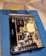
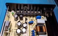
OK, here's my update to close the loop on using the B1304 case to mount the Meanwell LRS-150-24 PSU. I went ahead and ordered the power supply and spent a couple of hours (plus) cutting and drilling my B1304 to mount it in. I discovered that it IS possible to add a clip-in type IEC socket, but you have to remove the perforated top shield to give clearance to do so. (Note: a screw-mount type with 'ears' is too wide to fit, either vertically or horizontally.) However, given this is a solid aluminum box, the loss of the shield is no big deal. You'll also see that I added a panel-mount fuse holder, but you could use an inline holder, or even omit a fuse entirely (on your head be it).
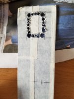
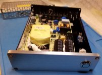
The worst part of the mechanical work is mounting the power supply. There are few decent mounting holes, and two of them are blind threaded holes, requiring careful measurements and drilling to align everything correctly. OK the other worst part was cutting the hole for the IEC socket. Turns out the rear end-plate of the case I had was much thicker than I usually see on such cases. So it took quite a while to drill rows of holes and dremel and hand-file the square hole to fit the IEC clip socket (first pic - in progress).
I've included pics after the parts are all test mounted (prior to wiring). With 20-20 hindsight, I'd have put the DC socket way over to the other side, above the voltage adjust pot. But too late now.
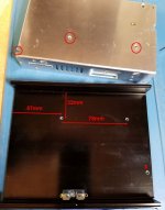
To save you having to re-invent the wheel
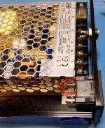
, one of the pics shows the hole positions/measurements (to hole centers) for the blind holes to mount the PSU. Obviously you should first verify these hole positions with your PSU, in case they are different. The 3rd hole (marked "X") I just marked from the top and drilled, after test-mounting the supply with the other two screws.Although I just removed the shield, actually, you could keep it... but you'd have to cut out a piece in the corner, to fit around the IEC (see the red dotted lines in the last pic).
All in all, I really like the end result. Very nice looking case and absolutely the smallest possible - and neatest - package to fit around that PSU.
Attachments
So I was checking the output from the LRS-150-24 power supply this morning. The adjustment pot can alter the output voltage in the range 20V to 30V (no load). Has anybody cranked this sucker up to 30V and tried it? That would give enough headroom to obviate the need to change that resistor on the 24V regulator in the FX502. Plus maybe a few more watts?
Not sure if cranking it up would harm or degrade anything in the power supply - or maybe cause more supply noise.
Not sure if cranking it up would harm or degrade anything in the power supply - or maybe cause more supply noise.
micro controller
Hi
refrence to pos 902
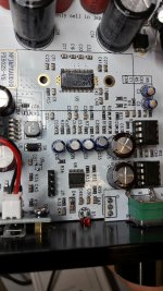
i just think about the µC and the magic 4 connectors what we miss at page 23 #228. https://www.diyaudio.com/forums/class-d/315681-tpa3250-listening-23.html#post5372662
look at pic:
https://www.diyaudio.com/forums/class-d/315681-tpa3250-listening-27.html#post5387876
i guess this are for "programming" the µC. maybe some µC guy can jump in here....
chris
Hi
refrence to pos 902
i just think about the µC and the magic 4 connectors what we miss at page 23 #228. https://www.diyaudio.com/forums/class-d/315681-tpa3250-listening-23.html#post5372662
look at pic:
https://www.diyaudio.com/forums/class-d/315681-tpa3250-listening-27.html#post5387876
i guess this are for "programming" the µC. maybe some µC guy can jump in here....
chris
Attachments
So, I wasn't sure that I believed that being magnetic (or not) proves (or not) that an NE5532 is fake. @ekbrus do you have any reference to base that on?
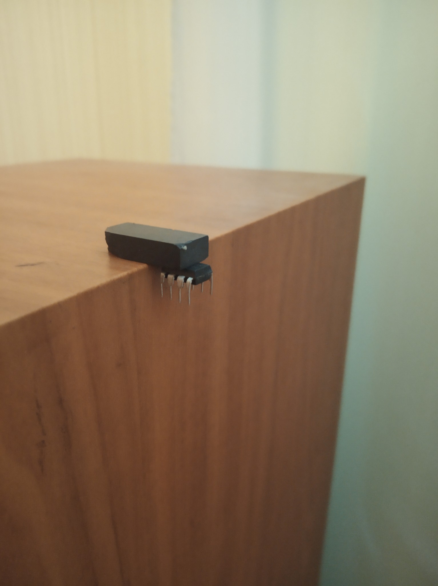
Having said that, I went to check some opamps I have loose. I tested a pair of ON Semiconductor SE5532's I got from a respected supplier (Arrow), with the pretty strong magnet at the end of a telescoping pickup tool. They were just magnetic - just enough to lift their own weight off the table. I then tried some TL082's (unknown provenance) and they had about the same level of magnetism as the SE5532's.
Then I tried the NE5532's that I'd previously taken out from my FX502S. A whole order of magnitude higher in magnetic attraction - they about leapt off the table when the magnet came near! Hmmm.
Don't know what this means, but it's a data point. Anyone else do a test? Preferably with known good NE5532's vs the 5532's out of your FX502S?
Fake newsmaximum deshovy production technology fake ne5532p. in my fx502s pro at the output of ne5532p were electrolytes SamYoung, replaced by tantalum AVX TAP106M035SRW
Wires of semiconductors are magnetic for decades
Last edited:
Fake news
Maybe so, but there's magnetic and there's MAGNETIC! Read my post above yours.
bought lm4562na/nopb and ne5532p today and compared by magnet. in fact, it speaks about different production technologies, no moreSo, I wasn't sure that I believed that being magnetic (or not) proves (or not) that an NE5532 is fake. @ekbrus do you have any reference to base that on?
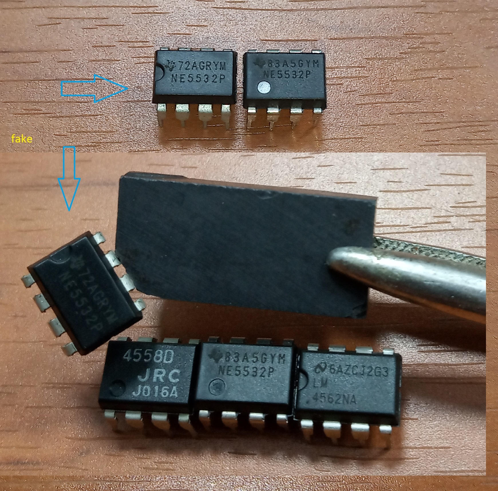
Please, resize the picture or use the thumb. It's really annoying.bought lm4562na/nopb and ne5532p today and compared by magnet. in fact, it speaks about different production technologies, no more
maximum deshovy production technology fake ne5532p. in my fx502s pro at the output of ne5532p were electrolytes SamYoung, replaced by tantalum AVX TAP106M035SRW
hi ekbrus
Sorry .. but i did not get your point about magnetic...i personally do not care if the fake opamp are magentic or not- i change it to "orign" onces
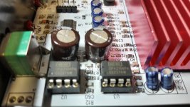
the Tantal 10µF after the output buffers (opamp) - AVX TAP106M035SRW as you described are instead off the 4 electrolytics. i am not an expert but i guess the TPA 32xx chip do not like DC on its inputs = INA, INB , INC, IND...with the tantal you maybe get some DC....
wait if some experts ...Voltwide/Doc give us an advise here...
chris
- Home
- Amplifiers
- Class D
- TPA3250 somebody is listening?