So I just swapped out the (fake?) opamps from my FX502spro and put in LME49720NA.
The problem now is that I have a significant crackling sound in my right channel that I'm fairly certain wasn't there before
Is there any chance that I broke something when I opened the amp, maybe by pressing too hard on the board when inserting the opamps?
Or what else is it likely to be?
sorry for you...

did you really check the direction of the opamps...pin 1....pin 8 orientation!!!!
https://www.diyaudio.com/forums/class-d/315681-tpa3250-listening-36.html#post5410854
check visually if every pin is in the socket correctly
and no...there is not a really chance that you push sooo hard that the pcb is broken....i guess
put them out and the fake in-.....is the crack still here?
Last edited:
put them out and the fake in-.....is the crack still here?
Great idea, thanks! Did this and the crackle is gone, phew!
Got the new opamps from a reputable store, faulty I guess?!
Great idea, thanks! Did this and the crackle is gone, phew!
Got the new opamps from a reputable store, faulty I guess?!
very very seldom that a repudiate store send you cracked chip...
but ok...crack is gone and the amp is playing music
but -->go ahead find the failure !...
mark your new opamps and change one after the other into the board.
e.g.
socket 1 old opamp
socket 2 new opamp1 - new opamp2
socket 1 new opamp1 - new opamp2
socket 2 old opamp
chris

..Wrong datasheet TPA3250...april2016
i want ot look at the implementation of a bigger cap e.g. 470µF at AVDD
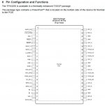
i found that the chapter 6 and the chapter 10.2 show different pin layouts!!!
pic 1 is the correct pin layout of tpa3250
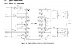
pic 2 is the wrong BTL-application it shows the TPA3251
TPA3250 and TPA3251 are mirrored at pin 8 9 and 14 15 !!! (irribeo told me that a long time ago..
chris
i want ot look at the implementation of a bigger cap e.g. 470µF at AVDD
i found that the chapter 6 and the chapter 10.2 show different pin layouts!!!
pic 1 is the correct pin layout of tpa3250
pic 2 is the wrong BTL-application it shows the TPA3251
TPA3250 and TPA3251 are mirrored at pin 8 9 and 14 15 !!! (irribeo told me that a long time ago..
chris
Attachments
Hi
yesterday night i go ahead with something light...
...are the FX doing some additional gain?....yes the implementation with volume knob do this!
yesterday night i did some short quick measurments with my diff probe of the scope
the input into the amp was set with 100mVrms / 1khz and at the pin 1 (outA) give me different voltages depending of the position the volume knob. this is logical and this is why we have a volume knob
the position with no gain is about 1 o clock. here i measure exactly what i set as input. 100mVrms/1khz
What i realize is if you set the volume knob more than 1 o clock, eg 2 o´clock position, i get "ringing" = the top of the sine is smeared and peaky, starting at 580mVrms/1khz rms input.
at 24V i got clear clipping at 690mvrms -46,7Vpp at 8R (34Watt)
additionally
yes i can confirm that the LM317 power up just the opamps.
the LM2596S is pushing 11,53V to the ams1117-3.3V for the logic chip (on off chip)
chris
Hi again
according to the upper study . the input of the tpa 3250 chip can handle max + - 3,9V input at all INPT_X entry so no trouble with additionally gain from the opamps to the chip....ok no problem at that point (datasheet table 6 for BTL)
my question is about gain up or down at the opamps soundwise? could that be that if we change with the volume knob the gain that some opamp chip do something "different" soundwise????
can i measure this with scope? or just with THD equipment?
chris
according to the upper study
. the input of the tpa 3250 chip can handle max + - 3,9V input at all INPT_X entry so no trouble with additionally gain from the opamps to the chip....ok no problem at that point (datasheet table 6 for BTL)my question is about gain up or down at the opamps soundwise? could that be that if we change with the volume knob the gain that some opamp chip do something "different" soundwise????
can i measure this with scope? or just with THD equipment?
chris
Last edited:
Maybe you measure some high frequency ringing that is above the audio band and thus inaudible. Sometimes you see inaudible things on the scope, sometimes you hear distortions your scope does not show you. Could you show a screenshot of your ringing?
yes i will...evening..
yes ofc it will improve the sound because the more you reduce gain the more feedback you feed in OPamp...
How this should be set up ideally is to generate sinewave from the sound source you usually use and fit the gain of OPamp to the value the outputstage starts to slightly clip. This way you will get best possible results on your system. You just have to measure the amp output slightly before the clipping and measure the input signal that goes to TPA what amplitude it has. Afterwards just recalculate gain of the OPamp to get that amplitude and you get the solution to suit your needs so the max volume knob position will represent max volume before clipping.
How this should be set up ideally is to generate sinewave from the sound source you usually use and fit the gain of OPamp to the value the outputstage starts to slightly clip. This way you will get best possible results on your system. You just have to measure the amp output slightly before the clipping and measure the input signal that goes to TPA what amplitude it has. Afterwards just recalculate gain of the OPamp to get that amplitude and you get the solution to suit your needs so the max volume knob position will represent max volume before clipping.
yes ofc it will improve the sound because the more you reduce gain the more feedback you feed in OPamp...
How this should be set up ideally is to generate sinewave from the sound source you usually use and fit the gain of OPamp to the value the outputstage starts to slightly clip. This way you will get best possible results on your system. You just have to measure the amp output slightly before the clipping and measure the input signal that goes to TPA what amplitude it has. Afterwards just recalculate gain of the OPamp to get that amplitude and you get the solution to suit your needs so the max volume knob position will represent max volume before clipping.
Hi Wiliks
ofc?
yes yesterday night i try something around with the volume knob and some reading on the scope. i was too tired to store pics on scope and post it here...
yes the position of the knob i found out - 1 o´clock 690mVrms max output = 46,7Vpp, 8R = 34 WATT with 24V supply
short..
if i look into the datasheet of opamp 4562 + BB2134 there are lot of graphs which shows that the opamp is working with under 1V output it has bad THD values. the problem is that you get no graph with the single 24V supply i use and the gain is not clear now from the opamp, but the gain is vary in THD too(datasheet) .e.g BB2134 figure 1 chapter 6.5
approx. Gain 1 THD = 0,0001
Gain 10 THD 0,001
chris
Last edited:
ofc = of course
you just need to find the opamp feedback resistors and reduce its values... also as you noted it uses unbalanced power supply and output capacitors, you can put foil capacitors from the bottom of the board in parallel to these, that can improve sound even further if you haven't done so already. About 100nF to 1uF capacitors...
you just need to find the opamp feedback resistors and reduce its values... also as you noted it uses unbalanced power supply and output capacitors, you can put foil capacitors from the bottom of the board in parallel to these, that can improve sound even further if you haven't done so already. About 100nF to 1uF capacitors...
ofc = of course
you just need to find the opamp feedback resistors and reduce its values... also as you noted it uses unbalanced power supply and output capacitors, you can put foil capacitors from the bottom of the board in parallel to these, that can improve sound even further if you haven't done so already. About 100nF to 1uF capacitors...
Hi
THX
i did this on post 521
https://www.diyaudio.com/forums/class-d/315681-tpa3250-listening-53.html#post5423051
and a lot pages before some other improvements
or not for my excuse i start as noob and i am still not really confident with measruments and other things
...but this is DIYchris
Hi
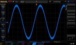
24Vpsu -1khz tone into rca R+L..8R load
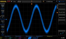
knob at 1 o´clock give me the input on the opamp exactly what i set into the rca input = 100mvrms - pic 1
output is 6,8Vpp ...Gain is about 33 dB
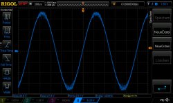
knob at 11 o´clock give me about 50mVrms at the opamps with 100mVrms input and at to output 3,76vpp..its 34dB gain pic 2
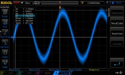
knob at max give me about 209mVrms at the opamps with 100mVrsm input and at to output 32,9vpp..its 32,3dB gain pic 3
so the tpa 3250 has a gain of 26db so with this opamps config i get about 33db so its 7db more gain
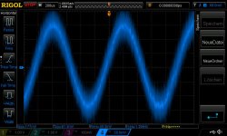
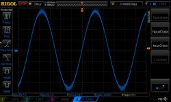
800mV input and the knob at the max give me the clipping at 24V with 45,6Vpp at 8R...pic 4
pic 5 is a test of asymmetric signal on the opmap..not much but visible...why?
pic 6 is with 30V/6Amp psu and 820mVrms and knob until clipping and 5-10seconds the amp switch off.
55,7Vpp ...8R= 48Watt
chris
24Vpsu -1khz tone into rca R+L..8R load
knob at 1 o´clock give me the input on the opamp exactly what i set into the rca input = 100mvrms - pic 1
output is 6,8Vpp ...Gain is about 33 dB
knob at 11 o´clock give me about 50mVrms at the opamps with 100mVrms input and at to output 3,76vpp..its 34dB gain pic 2
knob at max give me about 209mVrms at the opamps with 100mVrsm input and at to output 32,9vpp..its 32,3dB gain pic 3
so the tpa 3250 has a gain of 26db so with this opamps config i get about 33db so its 7db more gain
800mV input and the knob at the max give me the clipping at 24V with 45,6Vpp at 8R...pic 4
pic 5 is a test of asymmetric signal on the opmap..not much but visible...why?
pic 6 is with 30V/6Amp psu and 820mVrms and knob until clipping and 5-10seconds the amp switch off.
55,7Vpp ...8R= 48Watt
chris
Attachments
-
 fx1oclock knob_100mvrms in_24Vpsu_opamp.jpg75.3 KB · Views: 438
 -
 fx11oclock knob_100mvrms in_24Vpsu_opamp.jpg77.9 KB · Views: 439
 -
 fxmax knob_100mvrms in_24Vpsu_opamp.jpg74.3 KB · Views: 408
 -
 fx 800mVrmsin_24Vpsu.jpg74.6 KB · Views: 409
 -
 fx 1khz_asym.jpg83.1 KB · Views: 406
 -
 fx 820mVrmsin psu30V.jpg74.4 KB · Views: 52
Last edited:
Maybe you measure some high frequency ringing that is above the audio band and thus inaudible. Sometimes you see inaudible things on the scope, sometimes you hear distortions your scope does not show you. Could you show a screenshot of your ringing?
the ringing is always some voltage before clipping i guess that "normal"
Interesting gain measurements, thanks for that! they probably designed amplifier the way so also weak mobile phone signals can drive the amp to full power.
and ohh that class D.... it messes the signal quite badly a lot of ringing or jitter or what the hell is that, doh...
Your test with 30V PSU is interesting, were both channels driven or just one? turn off is it due to heatsink temperature or just chip not capable to dissipate heat into the heatsink fast enough? have you tried 30V PSU with normal musical signal (not continuous sine wave) if that turn off too?
and ohh that class D.... it messes the signal quite badly
a lot of ringing or jitter or what the hell is that, doh...Your test with 30V PSU is interesting, were both channels driven or just one? turn off is it due to heatsink temperature or just chip not capable to dissipate heat into the heatsink fast enough? have you tried 30V PSU with normal musical signal (not continuous sine wave) if that turn off too?
Interesting gain measurements, thanks for that! they probably designed amplifier the way so also weak mobile phone signals can drive the amp to full power.
and ohh that class D.... it messes the signal quite badly
Your test with 30V PSU is interesting, were both channels driven or just one? turn off is it due to heatsink temperature or just chip not capable to dissipate heat into the heatsink fast enough? have you tried 30V PSU with normal musical signal (not continuous sine wave) if that turn off too?
Hi Wiliks
I am happy with your comments. that nice that you read my posts and give feedback
partly the signals getting messy with the modulatet carrier frequency of about 480khz PWM.
i always power both channels continiously 1khz!
the chip was in this case not connected with the heatsink because i checked about the AVDD and keep the board as it is naked (without buttom alu case too)
as i learned by irribeo and doctor:
the TPA3250 chip is a chip which has the power pad (dissapation of heat) under the chip! - so the pcb layout design is very important and the cooling with heatsink on the top is something less additionally. i picked up the idea by doctor at his development of a tiny amp. he use a thermal pad under the chip to connect his to the alu case.
TPA3251 (TPA3255) aka “Model Tiny” in Aluminiumgehause – #360customs
i personally use a ceramic resistor. additionally to this its very important that the thermal paste under the chip is implemented! in my board its not look so
chris
from post 775
so the tpa 3250 has a gain of 26db so with this opamps config i get about 33db so its 7db more gain
is that correct?
so the volume knob- potentiometer is a voltage divider for the input and the inverted opamp has a gain about 7db....correct?
which values should i find an the pcb to get this? can some fresh brain and expert help me?
thanks chris
Attachments
he use a thermal pad under the chip to connect his to the alu case.
TPA3251 (TPA3255) aka “Model Tiny” in Aluminiumgehause – #360customs
i personally use a ceramic resistor. additionally to this its very important that the thermal paste under the chip is implemented! in my board its not look so
The IC shown there is a TPA3251 with thermal pad on top.
- Home
- Amplifiers
- Class D
- TPA3250 somebody is listening?