Correction, I have the EVM configured for BTL mode not PBTL (2 speakers), one of two speaker has decreased volume by approx. 6dB.I decided to change the 4 caps in the output filter to better fit my two 8 ohm speakers which I am running in PBTL mode.
So far this does not alter my assumption.Correction, I have the EVM configured for BTL mode not PBTL (2 speakers), one of two speaker has decreased volume by approx. 6dB.
I do not know the details of your PCB.
All I can say the TPA3255 needs symmetrical input drive in any BTL configuration.
To check the outputs, drive your input with some music,
take a loudspeaker
1 terminal connected to GND
Connect the other terminal through a series cap of 470uF/35 or more, to each single PBTL output.
Cap-/cap+ connected to speaker/PBTL - output respectively.
This test should show one working output and one silent output.
In case your measurements confirm my assumptions, the next steps are
Check the input of the silent channel for audio signal.
If there is none (my assumption) you should trace back the driving analog front end block, with its jumper settings, operational amps etc.
Last edited:
I'm going to test it with some music and attach a scope. If there is no anomaly I'll try the second part which IIRC is running it in SE mode?So far this does not alter my assumption.
I do not know the details of your PCB.
All I can say the TPA3255 needs symmetrical input drive in any BTL configuration.
To check the outputs, drive your input with some music,
take a loudspeaker
1 terminal connected to GND
Connect the other terminal through a series cap of 470uF/35 or more, to each single PBTL output.
Cap-/cap+ connected to speaker/PBTL - output respectively.
This test should show one working output and one silent output.
In case your measurements confirm my assumptions, the next steps are
Check the input of the silent channel for audio signal.
If there is none (my assumption) you should trace back the driving analog front end block, with its jumper settings, operational amps etc.
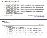
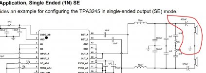
So I would need to reconfigure the jumpers to SE mode first as seen in the datasheet text in the attachment right?
I've also attached an image and I've circled the connection with a red marker that you are suggesting, did I understand it correctly?
Do TPA324X and TPA325x need a load on each of the outputs while it's on like the TPA311X needed it if you didn't want to destroy your outputs?
You advised retracing, I did not mess with any of the jumpers, this problem happened right after cap change to a smaller value, the volume was balanced before that no matter which device I used to drive it (DAC, Android phone, both via RCA cable). I'll try to retrace If I find the silent output.
Is it possible that solely the wrong cap value (0.22uH paired with 7uH inductor) would cause this channel imbalance if it was soldered properly? This should only have an effect on gain/attenuation at the higher frequencies and even if it would cause volume change, it should be symetrical in all of the outputs, right?
Attachments
You can test in (P)BTL mode as well, both output legs should provide music, no need to set to SE.I'm going to test it with some music and attach a scope. If there is no anomaly I'll try the second part which IIRC is running it in SE mode?So I would need to reconfigure the jumpers to SE mode first as seen in the datasheet text in the attachment right?
With no load on the outputs there is no danger of destruction. In the worst case the chip protection triggers and shuts down immediately after turn on. But I did not experience this problem until now. Btw I am using my own designs, not that AliBaba stuff.I've also attached an image and I've circled the connection with a red marker that you are suggesting, did I understand it correctly?
Do TPA324X and TPA325x need a load on each of the outputs while it's on like the TPA311X needed it if you didn't want to destroy your outputs?
?
Agreed, I would expect it that way.You advised retracing, I did not mess with any of the jumpers, this problem happened right after cap change to a smaller value, the volume was balanced before that no matter which device I used to drive it (DAC, Android phone, both via RCA cable). I'll try to retrace If I find the silent output.
Is it possible that solely the wrong cap value (0.22uH paired with 7uH inductor) would cause this channel imbalance if it was soldered properly? This should only have an effect on gain/attenuation at the higher frequencies and even if it would cause volume change, it should be symetrical in all of the outputs, right?
Hi voltwide,You can test in (P)BTL mode as well, both output legs should provide music, no need to set to SE.
I've now been able to test each of the output with some music and a scope probe attached.
I do (hopefully) believe I located the output, that is not making any sound. See the attached picture please.
3 of the outputs have similar waveform when playing music (same as the upper one in the attached picture) and 1 is static DC like you predicted, if I'm interpreting this correctly?
So my next move would now be to check the input for this channel and the rest of the analog front end, and compare it to the other 3 inputs, that are obviously working fine.
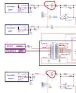
Is there any possibility, that the DC blocking caps don't have the same capacitance or rather there may be large variability between parts on different inputs (A,B,C and D). I will retest but I'm pretty sure I measured one of the 10uF electrolytic DC blocking caps having 13uF capacitance (DMM capacitance measurement).I've attached a part of schematic, where those parts are shown in circuit.
Could this have a significant effect in regard to input symmetry, that you mentioned in one of your previous posts?
If not, what would be the best way for me to start troubleshooting the inputs. Live circuit, power off...?
Good to know. Never happened to me, but I've read here never to power up a TPA311x without speakers or a dummy load. Can't remember if those 3ohm resistors on the output were bursting or if it was something else.With no load on the outputs there is no danger of destruction. In the worst case the chip protection triggers and shuts down immediately after turn on. But I did not experience this problem until now. Btw I am using my own designs, not that AliBaba stuff.
Interestingly, a lot of those output components that were regular in those TPA311x amps are now crossed out and omitted from the EVM's, at least in the TPA3244 and 3245 EVM's.
Thanks for the help!
Attachments
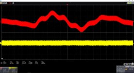
Yes, the yellow scope trace shows the silent output.
Both outputs traces show a bit of "smear" - which is caused by the clock ripple residue.
In other words: Both outputs are operating - but the yellow is not fed with audio signal at its input.
Great, we are on the right track.
Coupling caps with 13uF instead of 10uf are not suspect at all - 20~50% tolerance normally does not matter here.
So you should trace now the signal path leading to the input without signal.
Often you can read these warnings not to drive class-d-amps w/o load - an opinion I simply do not share.
Last edited:
Well good news, the silent output channel came alive after I probed all the input channels and found no differences between inputs.Coupling caps with 13uF instead of 10uf are not suspect at all - 20~50% tolerance normally does not matter here.
So you should trace now the signal path leading to the input without signal.
.

The only theory I have is, that one of the headers could've become unseated while I was flipping the board over while changing caps.
Whatever was wrong, it now seems to be sorted. I appreciate the help!
3255EVM in BTL Mode 2.0 - Balanced Wiring
Hi all,
My first post on the Forum.
I need some hints about TPA3255EVM.
I've been told on Ti forum to put J21 Out (no smoke or anything else noticed)
I actually use 2 SE Inputs (Stereo mode), it works perfectly.
My goal is to go Balanced.
From what I know I need to use J10 & J12 analog inputs.
It should be :
- For J10 : +/Gnd/- respectively INA/GND/INB
- For J12 : +/Gnd/- respectively INC/GND/IND
I know I have to switch J4 & J19 to DIFF position.
Should I have to do something else ?
Do you think I miss another point ?
Thank you for your answers.
Regards
The schematic is page 17 not 18.
The thing that confused me is that I think J10 should be named
INA/B DIFF INPUT instead of INC/D DIFF INPUT, (just like J12)
And they should never be jumpered (tables correctly always show 'out') but are included in the tables so people don't as J4 and J19 are used for selecting between SE and DIFF.
You can use J10 and J12 or use the rca (2 per channel) connectors as differential inputs. On page 17 you can see that they are the same.
You could connect the balanced inputs to the audio interface board, pins 11, 13, 15, and 17. Connect ground to pin 21. I think a 20 awg solid wire can easily be pushed into each pin.
This would bypass the op amps, and leave only the 10uf coupling capacitor in the signal path.
The chip's input impedance is 20k.
Mike
This would bypass the op amps, and leave only the 10uf coupling capacitor in the signal path.
The chip's input impedance is 20k.
Mike
I recently found these for this purpose and many more.
10PC Female&Male 40pin 2.54mm Header Socket Single Row Strip PCB Connector CA | eBay $1

10PC Female&Male 40pin 2.54mm Header Socket Single Row Strip PCB Connector CA | eBay $1
You could connect the balanced inputs to the audio interface board, pins 11, 13, 15, and 17. Connect ground to pin 21. I think a 20 awg solid wire can easily be pushed into each pin.
This would bypass the op amps, and leave only the 10uf coupling capacitor in the signal path.
The chip's input impedance is 20k.
Mike
Many thanks Mike
I'll go this way.
Best regards
I'd like to put the RESET switch on the front panel.
Could you confirm that Pin 10 of J28 need to be connected to one side of the switch and the other side to Pin 22 (Gnd) ?
According to the schematic, that should work. You could test this by using a jumper wire (starting to wonder if 22 awg is better), and connect pins 10 and 22.
Seems like others have inquired about this, but not sure if anyone has actually tried it.
Let us know it that works.
Mike
Hi,
"You could connect the balanced inputs to the audio interface board, pins 11, 13, 15, and 17. Connect ground to pin 21. I think a 20 awg solid wire can easily be pushed into each pin."
Today, I connect as you say, but nothing at the output.
Some plops could be haerd in speakers, I quickly power off the amp.
Maybe am I wrong with jumpers settings...
I leave them in SE configuration (stereo mode using RCA inputs).
Some hints are welcome
Regards
Last edited:
ABSNimes, regarding differential input to the 3255EVM board, in stereo BTL mode, there are two slightly different approaches;
i) connect to the J10 and J12 headers (or all 4x RCA connectors, which I consider confusing) -
your audio signals will still be buffered by the NE5532 opamps, but remain fully differential.
ii) connect to pins 11,13,15,17 & 21-GND of the J28 header (as member mboxler suggested)
your audio signals will then bypass the opamps, and go to the TPA3255 simply via a DC blocking cap.
Which approach sounds better will likely depend on whether your particular source device benefits from a buffer in the chain. I suggest you try i) first.
Check your configuration - you want the board in 2 x BTL mode, with differential inputs;
J5(M1), J6(M2) should be in the "0" or "L" position.
J21, J7, J8 should be open.
J4, J19 should be in the "DIFF" position.
J26 should be in the "C" position.
J27 should be in the "D" position.
S1 should be in the "NORMAL" position.
If this works OK, and you want to then try ii)
I understand that the opamps should be grounded, since they will then be unused, and might otherwise generate some noise (or heat).
I went overboard trying to mod my TPA3250EVM board and I just killed it.
I now have a very nice chassis, which contains a 32V Connex SMPS within a separate metal sub-frame, so I will go ahead and buy another amp board ...
but your opinions, please; would the TPA3251 board be equally suitable for me?
Apart from the suitability of my power supply, please bear in mind that I will be driving MarkAudio fullrange speakers (6 ohm) at low-to-moderate listening levels.
Thanks.
- Home
- Amplifiers
- Class D
- TI TPA3255EVM